Toyota 4Runner: Components
COMPONENTS
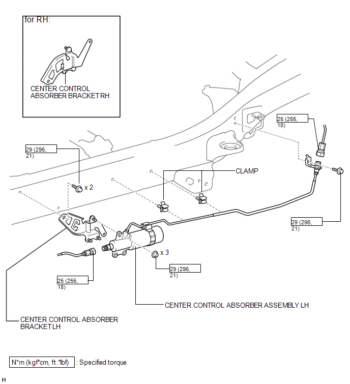
ILLUSTRATION
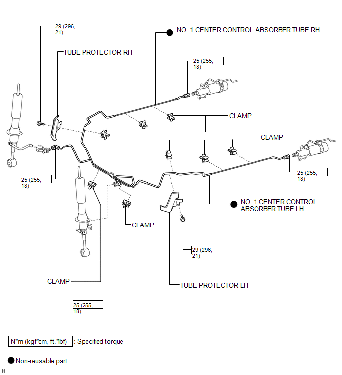
ILLUSTRATION
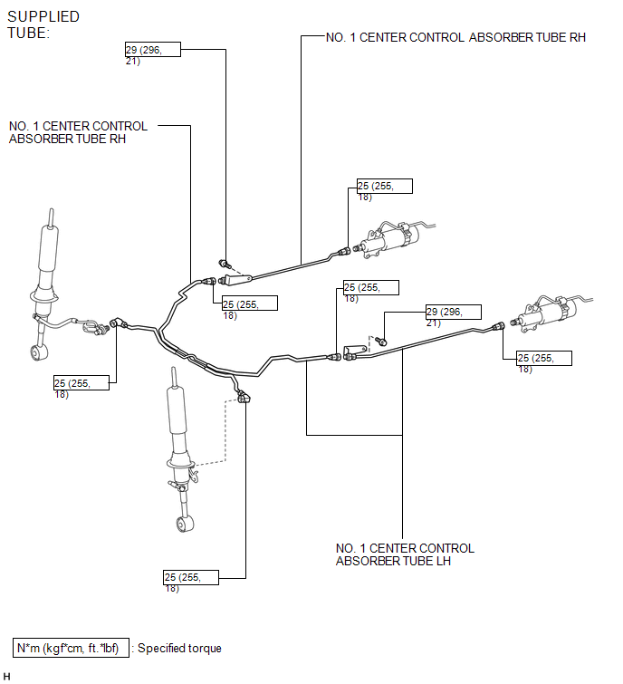
ILLUSTRATION

 Removal
REMOVAL
CAUTION / NOTICE / HINT
NOTICE:
Be sure to read PRECAUTION before performing this procedure (See page
).
PROCEDURE
1. REMOVE FRONT WHEEL
2. REMOVE REAR WHEEL
3. REMOVE CENTER CONTROL ...
Other materials about Toyota 4Runner:
Accessory Meter
Components
COMPONENTS
ILLUSTRATION
Removal
REMOVAL
PROCEDURE
1. DISCONNECT CABLE FROM NEGATIVE BATTERY TERMINAL
CAUTION:
Wait at least 90 seconds after disconnecting the cable from the negative (-)
battery terminal to disable the SRS system.
N ...
Sound Quality is Bad Only when Disc is Played (Volume is Too Low)
CAUTION / NOTICE / HINT
NOTICE:
After replacing the navigation receiver assembly of vehicles subscribed to pay-type
satellite radio broadcasts, XM radio ID registration is necessary.
PROCEDURE
1.
REPLACE DISC AND RECHECK
...
© 2016-2026 | www.to4runner.net

0.0068
0.0068