Toyota 4Runner: Components
Toyota 4Runner Service Manual / Vehicle Interior / Seat / Front Seat Assembly(for Manual Seat) / Components
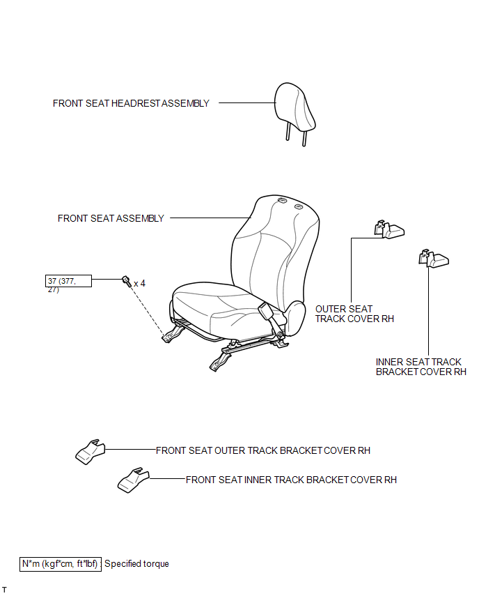
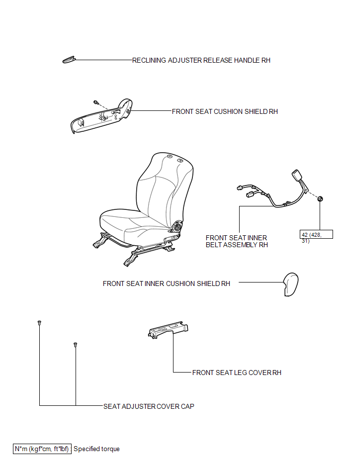
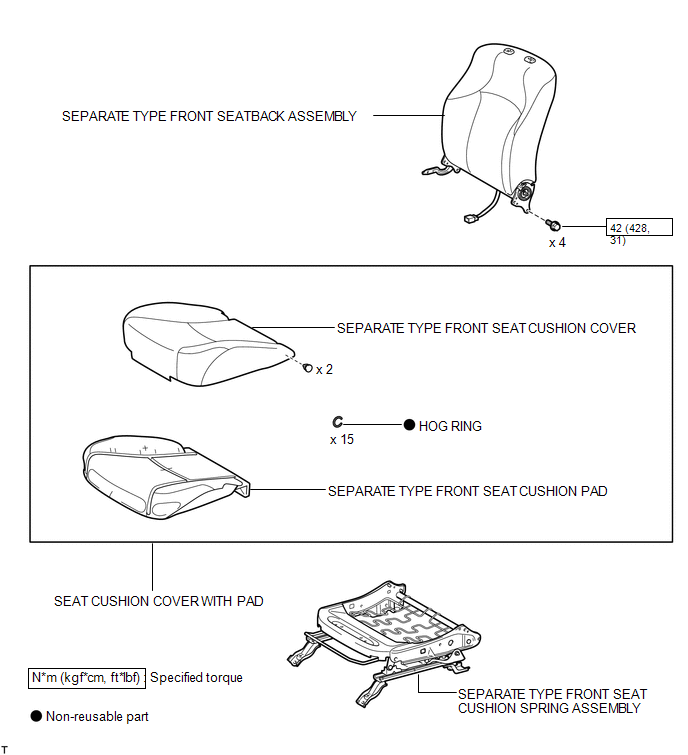
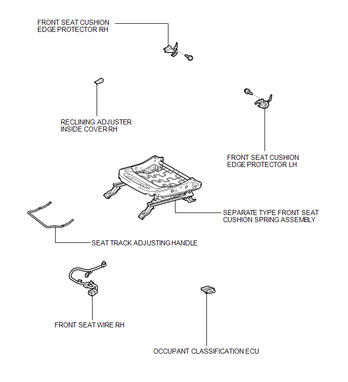
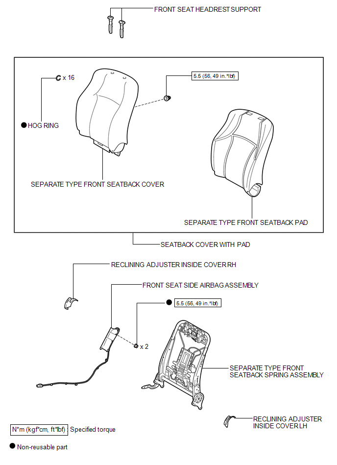
COMPONENTS
ILLUSTRATION
ILLUSTRATION
ILLUSTRATION
ILLUSTRATION
ILLUSTRATION

 Removal
REMOVAL
CAUTION / NOTICE / HINT
CAUTION:
Wear protective gloves. Sharp areas on the parts may injure your hands.
HINT:
The procedure listed below is for the RH side.
PROCEDURE
1. PRECAUTION
...
Other materials about Toyota 4Runner:
Green And Red Indicators Do Not Come On When Ig-on
DESCRIPTION
If the red and green indicators fail to illuminate after the ignition switch
is turned to ON, the vehicle does not recognize the DCM (Telematics Transceiver).
The DCM (Telematics Transceiver) connectors may have been disconnected or the DCM
...
How To Proceed With Troubleshooting
CAUTION / NOTICE / HINT
HINT:
Use these procedures to troubleshoot the power door lock control system.
*: Use the Techstream.
PROCEDURE
1.
VEHICLE BROUGHT TO WORKSHOP
NEXT
...
© 2016-2026 | www.to4runner.net

0.0074
0.0074