Toyota 4Runner: Components
COMPONENTS
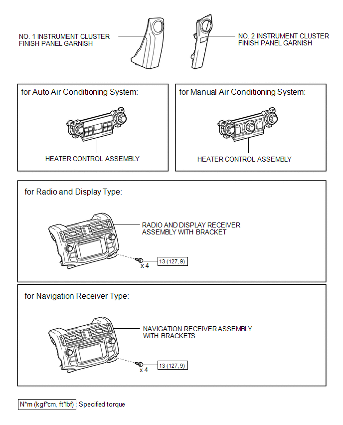
ILLUSTRATION
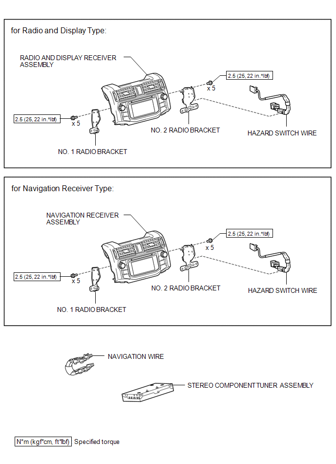
ILLUSTRATION

 Removal
REMOVAL
PROCEDURE
1. DISCONNECT CABLE FROM NEGATIVE BATTERY TERMINAL
(See page )
2. REMOVE NO. 1 INSTRUMENT CLUSTER FINISH PANEL GARNISH
3. REMOVE NO. 2 INSTRUMENT CLUSTER FINISH PANEL GARNIS ...
Other materials about Toyota 4Runner:
Outside temperature display
The temperature display shows temperatures within the ranges of -40°F
(-40°C) and 122°F (50°C).
Vehicles without Multi-terrain Select
Vehicles with Multi-terrain Select
The outside temperature is displayed when Vehicles without a smart
key syste ...
Radio Receiver Power Source Circuit
DESCRIPTION
This is the power source circuit to operate the radio and display receiver assembly.
WIRING DIAGRAM
CAUTION / NOTICE / HINT
NOTICE:
Inspect the fuses for circuits related to this system before performing the following
inspection procedure. ...
© 2016-2026 | www.to4runner.net

0.0087
0.0087