Toyota 4Runner: Components
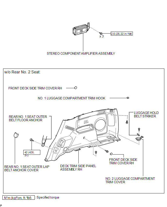
COMPONENTS
ILLUSTRATION
.png)
ILLUSTRATION
.png)
ILLUSTRATION
.png)
ILLUSTRATION
.png)
ILLUSTRATION

 Removal
REMOVAL
PROCEDURE
1. DISCONNECT CABLE FROM NEGATIVE BATTERY TERMINAL
NOTICE:
When disconnecting the cable some systems need to be initialized after the cable,
is reconnected (See page ).
2. RE ...
Other materials about Toyota 4Runner:
Sliding Roof ECU Power Source Circuit
DESCRIPTION
If the sliding function and tilt function do not operate, there may be a malfunction
in the sliding roof drive gear sub-assembly power source circuit.
WIRING DIAGRAM
CAUTION / NOTICE / HINT
NOTICE:
When the sliding roof drive gear ...
Dtc Check / Clear
DTC CHECK / CLEAR
1. CHECK DTC
HINT:
When DTC B1650/32 is stored as a result of troubleshooting for the airbag system,
perform troubleshooting for the occupant classification system.
(a) Connect the Techstream to the DLC3.
(b) Turn the ignition switch t ...
© 2016-2026 | www.to4runner.net

0.0249
0.0249