Toyota 4Runner: Components
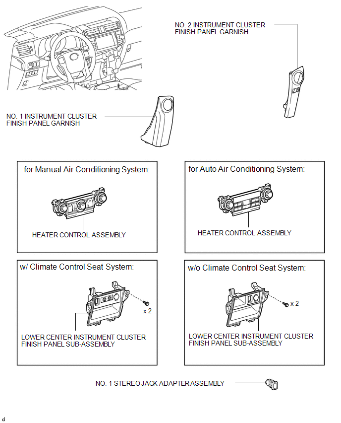
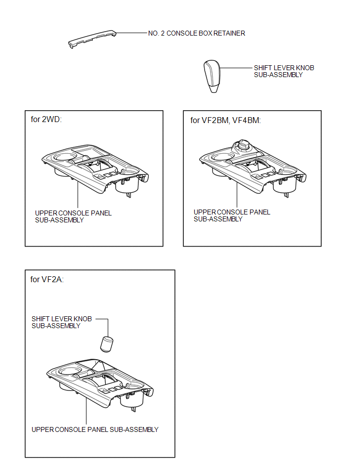
COMPONENTS
ILLUSTRATION
ILLUSTRATION

 Removal
REMOVAL
PROCEDURE
1. DISCONNECT CABLE FROM NEGATIVE BATTERY TERMINAL
CAUTION:
Wait at least 90 seconds after disconnecting the cable from the negative (-)
battery terminal to disable the SRS sys ...
Other materials about Toyota 4Runner:
Installation
INSTALLATION
PROCEDURE
1. INSTALL NO. 2 OIL COOLER TUBE SUB-ASSEMBLY
(a) Temporarily install the oil cooler tube to the fan shroud with bolt
A. Install bolt B and tighten it to the specified torque. Then tighten bolt
A to the specified to ...
Taillight Relay Circuit
DESCRIPTION
The main body ECU receives headlight dimmer switch information signals, and illuminates
the clearance lights, taillights and license plate lights.
WIRING DIAGRAM
CAUTION / NOTICE / HINT
NOTICE:
Inspect the fuses and bulbs for circuits rela ...
© 2016-2026 | www.to4runner.net

0.0161
0.0161