
Toyota 4Runner: Components
COMPONENTS
ILLUSTRATION
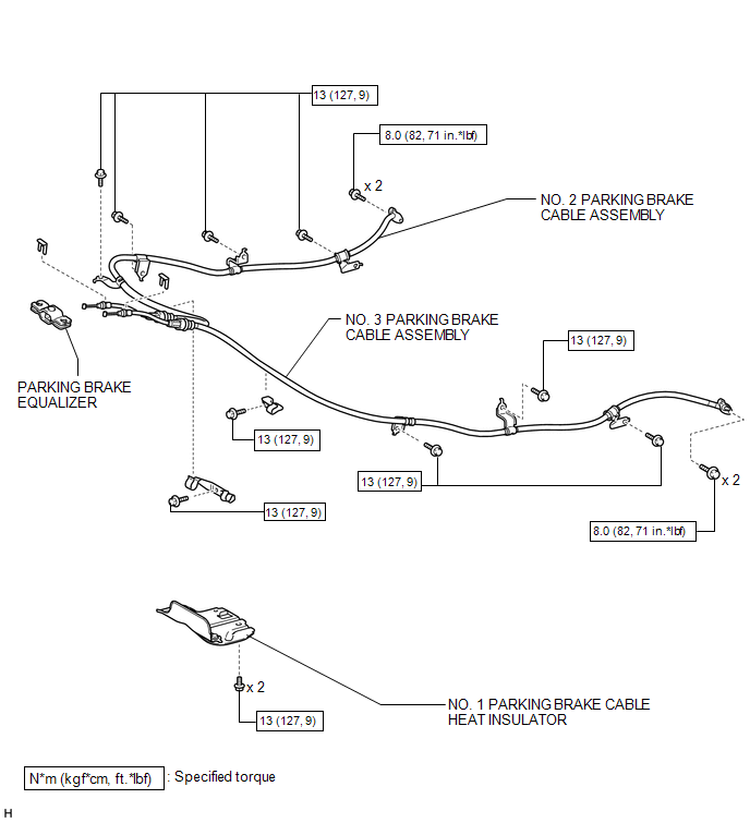

 Installation
INSTALLATION
PROCEDURE
1. INSTALL NO. 2 PARKING BRAKE CABLE ASSEMBLY
(a) Attach the claws of the No. 2 parking brake cable.
(b) Install the No. 2 parking brake cable assembly to the parking brake ...
Other materials about Toyota 4Runner:
Inspection
INSPECTION
PROCEDURE
1. INSPECT STEERING PAD SWITCH ASSEMBLY
(a) Inspect the steering pad switch assembly.
(1) Disconnect the switch connector.
Text in Illustration
*1
Up Switch
*2
Down Switch
...
Dtc Check / Clear
DTC CHECK / CLEAR
1. CHECK DTC
(a) Connect the Techstream to the DLC3.
(b) Turn the ignition switch to ON.
(c) Turn the Techstream on.
(d) Enter the following menus: Body Electrical / (desired system) / Trouble Codes.
(e) Read the DTCs.
2. CLEAR DTC
(a ...
© 2016-2026 | www.to4runner.net

0.025
0.025