Toyota 4Runner: Compressor Lock Sensor Circuit (B1422/22)
SYSTEM DESCRIPTION
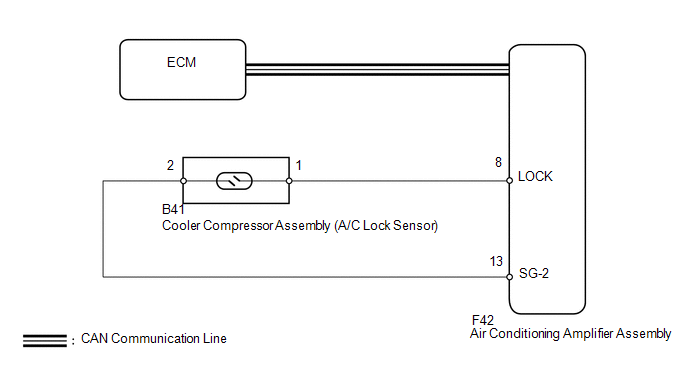
The ECM sends the engine speed signal to the air conditioning amplifier assembly via CAN communication.
The air conditioning amplifier assembly reads the difference between compressor speed and engine speed. When the difference becomes too large, the air conditioning amplifier assembly determines that the cooler compressor assembly is locked and turns the magnet clutch assembly off.
|
DTC Code |
DTC Detection Condition |
Trouble Area |
|---|---|---|
|
B1422/22 |
Open or short in the compressor lock sensor circuit. |
|
WIRING DIAGRAM
CAUTION / NOTICE / HINT
HINT:
As DTC B1422/22 is also output when the compressor drive belt is damaged or loose, inspect the belt before performing troubleshooting.
PROCEDURE
|
1. |
CHECK FOR DTC (CAN COMMUNICATION SYSTEM) |
(a) Use the Techstream to check if the CAN communication system is functioning normally.
Result|
Result |
Proceed to |
|---|---|
|
CAN DTC is not output |
A |
|
CAN DTC is output |
B |
| B | .gif) |
GO TO CAN COMMUNICATION SYSTEM |
|
.gif)
|
2. |
INSPECT COOLER COMPRESSOR ASSEMBLY (A/C LOCK SENSOR) |
|
(a) Remove the cooler compressor assembly (A/C lock sensor) (See page
|
|
.gif) ).
).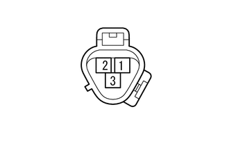
(b) Measure the resistance according to the value(s) in the table below.
Standard Resistance:
|
Tester Connection |
Condition |
Specified Condition |
|---|---|---|
|
1 - 2 |
20°C (68°F) |
160 to 320 Ω |
| NG | |
REPLACE COOLER COMPRESSOR ASSEMBLY (A/C LOCK SENSOR) |
|
|
3. |
CHECK HARNESS AND CONNECTOR (AIR CONDITIONING AMPLIFIER - A/C LOCK SENSOR) |
(a) Disconnect the F42 amplifier connector.
(b) Disconnect the B41 sensor connector.
(c) Measure the resistance according to the value(s) in the table below.
Standard Resistance:
|
Tester Connection |
Condition |
Specified Condition |
|---|---|---|
|
F42-8 (LOCK) - B41-1 |
Always |
Below 1 Ω |
|
F42-13 (SG-2) - B41-2 |
Always |
Below 1 Ω |
|
F42-8 (LOCK) - Body ground |
Always |
10 kΩ or higher |
|
F42-13 (SG-2) - Body ground |
Always |
10 kΩ or higher |
|
Result |
Proceed to |
|---|---|
|
OK (When troubleshooting according to problem symptoms table) |
A |
|
OK (When troubleshooting according to the DTC) |
B |
|
NG |
C |
| A | |
PROCEED TO NEXT SUSPECTED AREA SHOWN IN PROBLEM SYMPTOMS TABLE |
| B | |
REPLACE AIR CONDITIONING AMPLIFIER ASSEMBLY |
| C | |
REPAIR OR REPLACE HARNESS OR CONNECTOR |
 Ambient Temperature Sensor Circuit (B1412/12)
DESCRIPTION
The cooler thermistor (ambient temperature sensor) is installed in the front
part of the cooler condenser assembly to detect the ambient temperature and control
the air conditioning a ...
 Air Inlet Damper Control Servo Motor Circuit (B1442/42)
DESCRIPTION
The recirculation damper servo sub-assembly sends pulse signals to inform the
No. 1 air conditioning amplifier assembly of the damper position. The No. 1 air
conditioning amplifier as ...
Other materials about Toyota 4Runner:
Tire information
Typical tire symbols
1. Tire size
2. Summer tire or all season tires An all season tire has “M+S” on the
sidewall. A tire not marked “M+S” is a summer tire.
3. Uniform tire quality grading For details, see “Uniform Tire Quality
Grading” t ...
System Description
SYSTEM DESCRIPTION
1. SYSTEM DESCRIPTION
(a) The Electronic Controlled Automatic Transmission (ECT) is an automatic transmission
that electronically controls shift timing using the Engine Control Module (ECM).
The ECM detects electrical signals that indi ...

0.0077