Toyota 4Runner: Disassembly
DISASSEMBLY
PROCEDURE
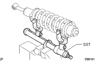
1. REMOVE FRONT SUPPORT TO FRONT SHOCK ABSORBER NUT
|
(a) Secure SST in a vise. SST: 09727-30021 09727-00010 09727-00031 SST: 09727-00060 |
|
|
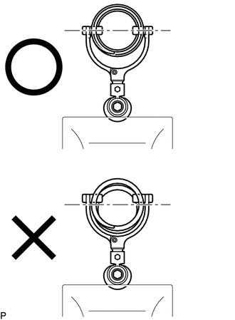
(b) Attach the arm of SST to the diameter of the front coil spring. CAUTION:
|
|
(c) Using SST, compress the front coil spring.
CAUTION:
- If the front coil spring bends during the compression, immediately stop the compression and reinstall SST.
- Do not compress the spring until the coil springs contact each other.
- Do not use an impact wrench. It will damage SST.
|
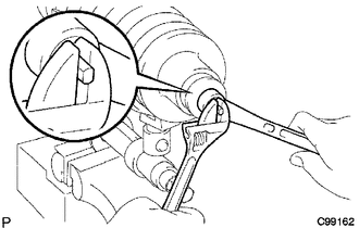
(d) Confirm that the front coil spring becomes free and remove the front support to front shock absorber nut. CAUTION: Do not remove the front support to front shock absorber nut when the front coil spring is not free. |
|
2. REMOVE FRONT SUSPENSION SUPPORT SUB-ASSEMBLY LH
(a) Remove the suspension support, cushion and 2 retainers from the shock absorber rod.
3. REMOVE FRONT COIL SPRING LH
(a) Remove the coil spring from the shock absorber.
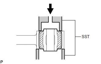
4. REMOVE FRONT SHOCK ABSORBER BUSH
|
(a) Using SST and a press, remove the absorber bush. SST: 09710-30012 09710-04071 09710-04081 |
|
 Removal
REMOVAL
CAUTION / NOTICE / HINT
NOTICE:
Be sure to read the precaution before performing this procedure (See page
).
HINT:
Use the same procedure for the RH and LH sides.
The proced ...
 Inspection
INSPECTION
PROCEDURE
1. INSPECT FRONT SHOCK ABSORBER ASSEMBLY LH
(a) Compress and extend the shock absorber rod and check that there is no abnormal
resistance or unusual sound during operation.
...
Other materials about Toyota 4Runner:
Runnable Signal Malfunction (B2286,P0335)
DESCRIPTION
The power management control ECU and ECM are connected by a cable and the CAN
communication lines. These DTCs are stored when the crankshaft position sensor signal
information from the cable and the crankshaft position sensor signal informatio ...
Mayday Battery
Components
COMPONENTS
ILLUSTRATION
Removal
REMOVAL
PROCEDURE
1. DISCONNECT CABLE FROM NEGATIVE BATTERY TERMINAL
NOTICE:
When disconnecting the cable, some systems need to be initialized after the cable
is reconnected (See page ).
2. REMOVE MA ...

0.0067