Toyota 4Runner: Disassembly
DISASSEMBLY
PROCEDURE
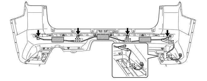
1. REMOVE NO. 3 FLOOR WIRE
(a) Disconnect the 4 connectors and remove the 3 pieces of tape.
(b) Detach the 4 clamps to remove the No. 3 floor wire.
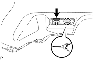
2. REMOVE REAR BUMPER SIDE BRACKET LH
|
(a) Remove the clip and 2 screws. |
|
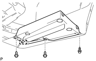
(b) Detach the guide to remove the rear bumper side bracket LH.
3. REMOVE REAR BUMPER SIDE BRACKET RH
HINT:
Use the same procedure as for the LH side.
4. REMOVE REAR BUMPER PLATE LH
|
(a) Remove the 2 outside moulding retainers. |
|
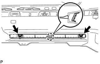
(b) Detach the claw to remove the rear bumper plate LH.
5. REMOVE REAR BUMPER PLATE RH
|
(a) Remove the outside moulding retainer. |
|
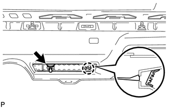
(b) Detach the claw to remove the rear bumper plate RH.
6. REMOVE NO. 1 REAR BUMPER PLATE
|
(a) Remove the outside moulding retainer. |
|
(b) Detach the claw to remove the No. 1 rear bumper plate.
7. REMOVE REAR BUMPER CENTER MOULDING
(a) Remove the 6 outside moulding retainers.
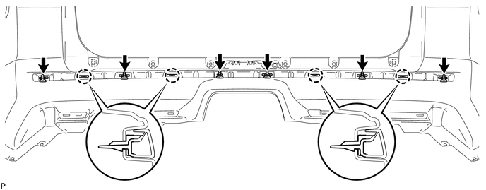
(b) Detach the 4 claws to remove the rear bumper center moulding.
8. REMOVE NO. 1 ULTRASONIC SENSOR
.gif)
9. REMOVE ULTRASONIC SENSOR CLIP
10. REMOVE NO. 2 ULTRASONIC SENSOR RETAINER
11. REMOVE NO. 1 ULTRASONIC SENSOR RETAINER
 Removal
REMOVAL
PROCEDURE
1. REMOVE JACK BOX HOLE COVER
2. REMOVE REAR QUARTER PANEL MUDGUARD LH
3. REMOVE REAR QUARTER PANEL MUDGUARD RH
HINT:
Use the same procedure as for the LH side.
4. REMOV ...
 Reassembly
REASSEMBLY
PROCEDURE
1. INSTALL NO. 1 ULTRASONIC SENSOR RETAINER
2. INSTALL NO. 2 ULTRASONIC SENSOR RETAINER
3. INSTALL ULTRASONIC SENSOR CLIP
4. INSTALL NO. 1 ULTRASONIC SENSOR
5. I ...
Other materials about Toyota 4Runner:
Outer Rear View Mirror Cover
Components
COMPONENTS
ILLUSTRATION
Removal
REMOVAL
CAUTION / NOTICE / HINT
HINT:
Use the same procedure for both the RH and LH sides.
The procedure listed below is for the LH side.
PROCEDURE
1. REMOVE OUTER MIRROR LH
(See page ...
Air Conditioning Control Panel Circuit
DESCRIPTION
This circuit consists of the heater control assembly and air conditioning amplifier
assembly. When the heater control assembly is operated, signals are transmitted
to the air conditioning amplifier assembly through the LIN communication system ...

0.0253