Toyota 4Runner: Disassembly
DISASSEMBLY
PROCEDURE
1. REMOVE SLIDING ROOF DRIVE GEAR SUB-ASSEMBLY
|
(a) Detach the bracket claw and remove the bracket. |
|
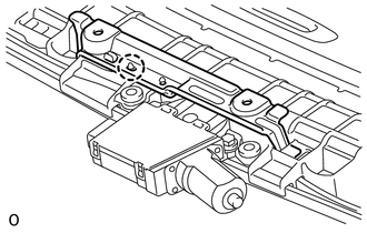
(b) Remove the 2 bolts and drive gear.
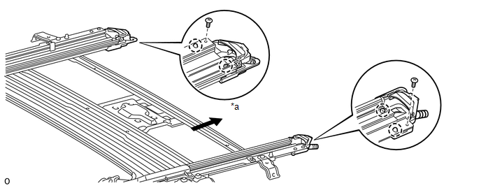
2. REMOVE SUNSHADE TRIM SUB-ASSEMBLY
 Text in Illustration
|
*a |
Rearward |
- |
- |
(a) Remove the 2 screws.
(b) Detach the 4 claws and remove the sliding roof piece LH and RH.
(c) Slide and remove the trim.
3. REMOVE SLIDING ROOF SUNSHADE STOPPER LH
|
(a) Remove the stopper. |
|
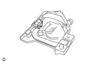
4. REMOVE SLIDING ROOF SUNSHADE STOPPER RH
HINT:
Use the same procedures described for the LH side.
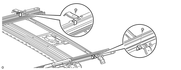
5. REMOVE SLIDING ROOF DRIVE CABLE SUB-ASSEMBLY
NOTICE:
Do not disassemble the sliding roof drive cable sub-assembly except when replacing it.
(a) Remove the 2 screws and 2 stoppers.
|
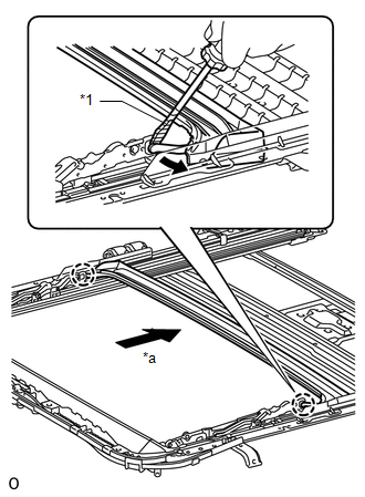
(b) Using a screwdriver, detach the 2 claws and slide the rear roof drip channel rearward to remove it. Text in Illustration
HINT: Tape the screwdriver tip before use. |
|
|
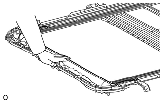
(c) Hold down the window deflector. |
|
|
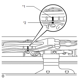
(d) Place matchmarks on the sliding roof drive cable sub-assembly at locations A and B as shown in the illustration. Text in Illustration
|
|
(e) Using a screwdriver, slide the sliding roof drive cable sub-assembly in the direction indicated by the arrow in the illustration to remove it.
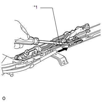 Text in Illustration
|
*1 |
Protective Tape |
.png) |
Slide |
HINT:
Tape the screwdriver tip before use.
 Removal
REMOVAL
PROCEDURE
1. DISCONNECT CABLE FROM NEGATIVE BATTERY TERMINAL
CAUTION:
Wait at least 90 seconds after disconnecting the cable from the negative (-)
battery terminal to disable the SRS sys ...
 Installation
INSTALLATION
PROCEDURE
1. INSTALL SLIDING ROOF HOUSING SUB-ASSEMBLY
(a) Temporarily install the housing with the 8 bolts (vehicle body side) and
8 nuts.
(b) Tighten the 8 nuts in alphabetical or ...
Other materials about Toyota 4Runner:
Relay(w/ Ptc Heater)
On-vehicle Inspection
ON-VEHICLE INSPECTION
PROCEDURE
1. REMOVE PTC HEATER RELAY (PTC NO. 1, PTC NO. 1, PTC NO. 3)
(a) Remove the 3 PTC heater relays from the engine room relay block.
Text in Illustration
*1
...
Power Seat Position is not Memorized
DESCRIPTION
When the seat memory SET switch and a memory switch (M1 or M2) are pressed simultaneously,
the main body ECU commands the position control ECU through CAN communication to
record the value of each position sensor.
WIRING DIAGRAM
CAUTION / ...

0.0071