Toyota 4Runner: Disassembly
DISASSEMBLY
PROCEDURE
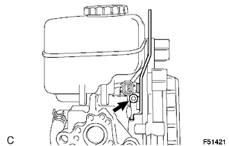
1. REMOVE NO. 1 BRAKE ACTUATOR BRACKET
|
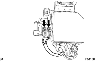
(a) Using a 5 mm hexagon wrench, remove the bolt and No. 1 brake actuator bracket. |
|
|
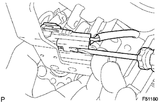
(b) Using a screwdriver, remove the brake fluid level warning switch connector from the No. 1 brake actuator bracket. |
|
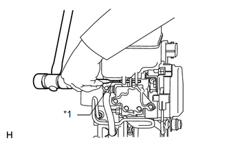
2. REMOVE BRAKE MASTER CYLINDER RESERVOIR SUB-ASSEMBLY
|
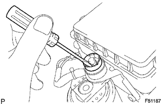
(a) Using a pin punch and hammer, remove the pin from the brake master cylinder reservoir. Text in Illustration
|
|
|
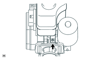
(b) Remove the screw and pull out the brake master cylinder reservoir sub-assembly. |
|
(c) Remove the master cylinder reservoir filler cap.
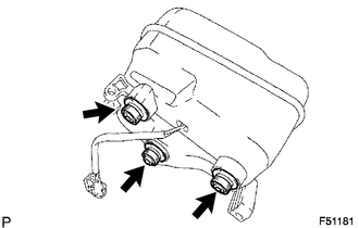
3. REMOVE MASTER CYLINDER RESERVOIR GROMMET
|
(a) Remove the 3 reservoir grommets from the master cylinder reservoir. |
|
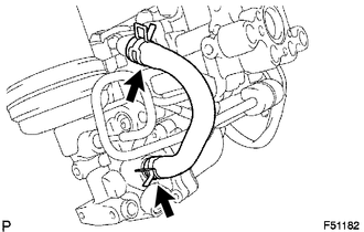
4. REMOVE NO. 1 BRAKE ACTUATOR HOSE
|
(a) Using needle nose pliers, slide the 2 clips and remove the brake actuator hose and 2 clips. |
|
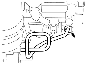
5. REMOVE NO. 1 BRAKE ACTUATOR TUBE
|
(a) Using a union nut wrench, remove the No. 1 brake actuator tube. |
|
6. REMOVE BRAKE BOOSTER WITH ACCUMULATOR PUMP ASSEMBLY
|
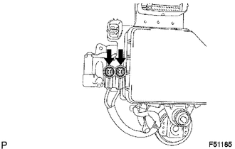
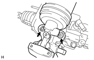
(a) Using a screwdriver, remove the 2 plugs. |
|
|
(b) Remove the 2 screws and disconnect the wire harnesses from the master cylinder solenoid. |
|
|
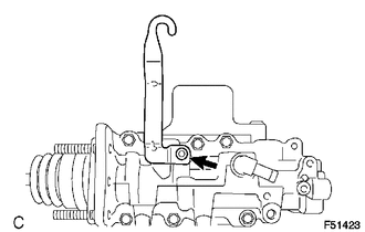
(c) Using a screwdriver, remove the clip. |
|
|
(d) Remove the brake booster with accumulator pump assembly from the brake master cylinder. |
|
(e) Remove the 2 brake booster pump collars and 2 brake booster pump bushes from the brake booster with accumulator pump assembly.
|
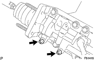
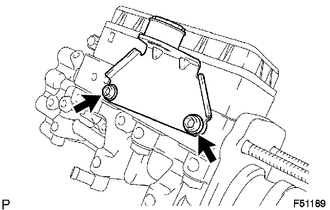
(f) Using a 4 mm hexagon wrench, remove the 2 pins. |
|
7. REMOVE NO. 1 BRAKE BOOSTER PUMP BRACKET
|
(a) Using a 5 mm hexagon wrench, remove the 2 bolts and No. 1 brake booster pump bracket from the brake master cylinder solenoid. |
|
(b) Remove the brake booster pump bush from the No. 1 brake booster pump bracket.
8. REMOVE NO. 3 BRAKE ACTUATOR BRACKET
|
(a) Remove the bolt and No. 3 brake actuator bracket from the brake master cylinder. |
|
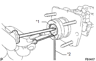
9. REMOVE BRAKE BOOSTER ACCUMULATOR PIPE
|
(a) Secure the brake booster with accumulator pump assembly in a vise. |
|
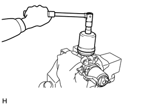
(b) Remove the brake booster accumulator.
(c) Remove the O-ring from the brake booster accumulator.
NOTICE:
Make sure no foreign matter enters the pump.
(d) Remove the brake booster accumulator pipe and compression spring.
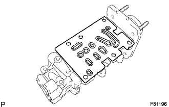
10. REMOVE MASTER CYLINDER SOLENOID
|
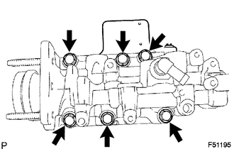
(a) Remove the 6 bolts and master cylinder solenoid. |
|
|
(b) Remove the gasket. |
|
11. REMOVE MASTER CYLINDER PUSH ROD CLEVIS
|
(a) Loosen the lock nut on the rod operating adapter and remove the push rod clevis and lock nut. |
|
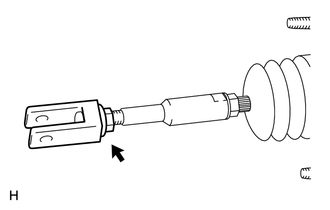
|
(b) Loosen the lock nut on the brake master cylinder side and remove the rod operating adapter and lock nut. |
|
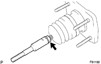
12. REMOVE MASTER CYLINDER BOOT
13. REMOVE BRAKE BOOSTER PISTON SUB-ASSEMBLY
|
(a) Pressing the piston in with a screwdriver, use a pin or equivalent to push the C-ring from the hole in the master cylinder body and then remove it with another screwdriver. Text in Illustration
HINT: Tape the screwdriver tip before use. |
|
(b) Remove the plug from the piston.
(c) Remove the piston by pulling it straight out, not at an angle.
NOTICE:
If the piston is pulled out at an angle, there is a possibility that the cylinder bore could be damaged.
 Removal
REMOVAL
CAUTION / NOTICE / HINT
NOTICE:
When installing, coat the parts indicated by arrows with lithium soap
base glycol grease (See page ).
As high pressure is applied to the bra ...
 Inspection
INSPECTION
PROCEDURE
1. INSPECT BRAKE BOOSTER PUMP ASSEMBLY
(a) Apply battery voltage to the brake booster pump cables, and check
the operation of the pump motor.
OK::
...
Other materials about Toyota 4Runner:
Reassembly
REASSEMBLY
PROCEDURE
1. INSTALL FRONT AXLE HUB OIL SEAL LH
(a) Using SST and a press, press in a new oil seal.
SST: 09608-36010
SST: 09950-70010
09951-07100
NOTICE:
Do not damage the oil seal.
...
Ambient Temperature Sensor Circuit (B1412)
DESCRIPTION
The cooler thermistor (ambient temperature sensor) is installed in the front
part of the cooler condenser assembly. This sensor is connected to the air conditioning
amplifier assembly and detects fluctuations in the ambient temperature. The se ...

0.0068