Toyota 4Runner: Disassembly
DISASSEMBLY
PROCEDURE
1. REMOVE REAR PROPELLER SHAFT UNIVERSAL JOINT SPIDER BEARING
HINT:
Use the same procedure for all rear propeller shaft universal joint spider bearing.
|
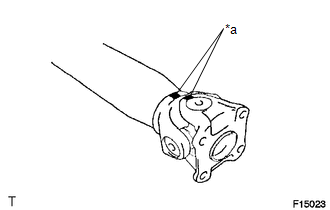
(a) Place matchmarks on the flange yoke and propeller shaft. Text in Illustration
|
|
|
(b) Using a brass bar and hammer, slightly tap in the spider bearing outer races. |
|
.png)
(c) Using 2 screwdrivers, remove the 4 snap rings from the grooves.
|
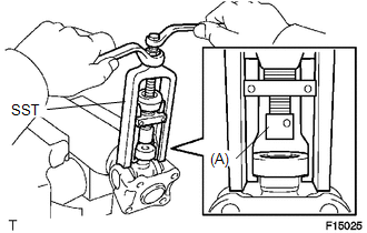
(d) Using SST, remove the spider bearing from the propeller shaft. SST: 09332-25010 HINT: Before installing SST, sufficiently raise the part labeled A. If the part labeled A is too low, it may be difficult to install SST. |
|
|
(e) Clamp the spider bearing outer race in a vise between aluminum plates and tap off the propeller shaft with a hammer. Text in Illustration
HINT: Remove the spider bearing on the opposite side using the same procedure. NOTICE: Do not tap the shaft. |
|
.png)
|
(f) Install the 2 removed spider bearing outer races to the universal joint spider. |
|
.png)
(g) Using SST, remove the bearing from the yoke.
SST: 09332-25010
HINT:
Before installing SST, sufficiently raise the part labeled A. If the part labeled A is too low, it may be difficult to install SST.
|
(h) Clamp the outer bearing race in a vise between aluminum plates and tap off the yoke with a hammer. Text in Illustration
|
|
.png)
(i) Remove the universal joint spider.
 Components
COMPONENTS
ILLUSTRATION
...
 Removal
REMOVAL
PROCEDURE
1. REMOVE PROPELLER SHAFT ASSEMBLY
(a) Place matchmarks on the propeller shaft flange and differential flange.
Text in Illustration
*a
...
Other materials about Toyota 4Runner:
Power Supply Drive Circuit (C1257)
DESCRIPTION
The motor relay (semiconductor relay) is built into the master cylinder solenoid
and drives the pump motor based on a signal from the skid control ECU.
DTC Code
DTC Detection Condition
Trouble Area
...
Terminals Of Ecu
TERMINALS OF ECU
1. CHECK AIR CONDITIONING AMPLIFIER ASSEMBLY
(a) Disconnect the F42 air conditioning amplifier connector.
(b) Measure the voltage and resistance according to the value(s) in the table
below.
Terminal No. (Symbol)
...

0.0105