Toyota 4Runner: Door Control Transmitter(w/ Smart Key System)
Components
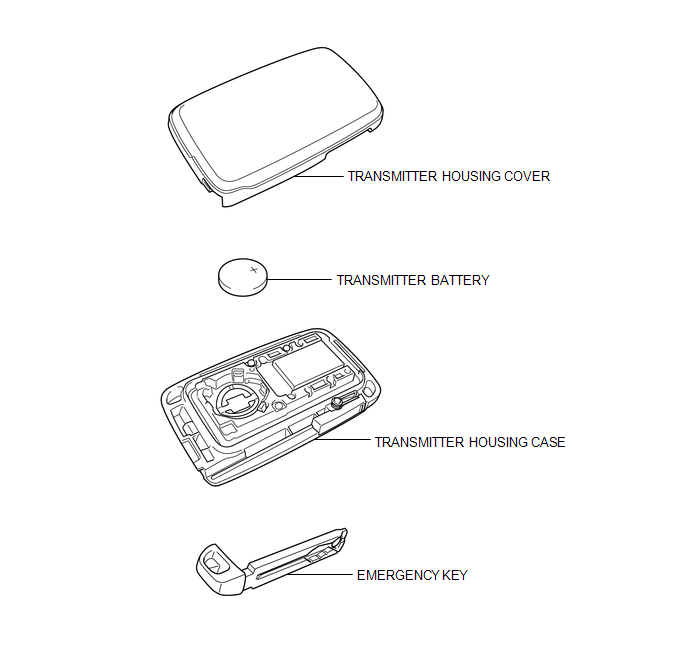
COMPONENTS
ILLUSTRATION
Removal
REMOVAL
CAUTION / NOTICE / HINT
NOTICE:
Take extra care when handling these precision electronic components.
PROCEDURE
1. REMOVE TRANSMITTER BATTERY
|
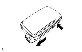
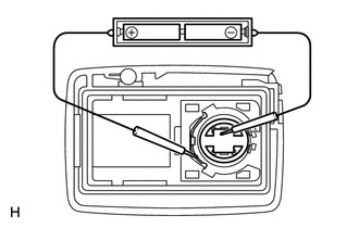
(a) Push the release hook knob and extract the emergency key. |
|
|
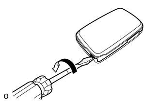
(b) Insert a precision screwdriver into the gap and turn the screwdriver to detach the transmitter housing cover. HINT: Tape the screwdriver tip before use. |
|
|
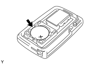
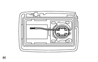
(c) Remove the battery (lithium battery: CR1632). NOTICE:
|
|
Inspection
INSPECTION
PROCEDURE
1. INSPECT TRANSMITTER BATTERY
(a) Inspect the operation of the transmitter.
(1) Remove the battery (lithium battery) from the transmitter (See page
.gif) ).
).
|
(2) Install a new or normal battery (lithium battery). HINT: If a new or normal battery is not available, first connect 2 new 1.5 V batteries in series. Then connect leads to the batteries and apply 3 V to the transmitter as shown in the illustration. |
|
(3) From outside the vehicle, approximately 1 m (3.28 ft) away from the driver side outside door handle, test the transmitter by pointing its key plate at the vehicle and pressing a transmitter switch, or while carrying the transmitter, touch the inside of the handle and pull it.
OK:
The door lock can be operated via the transmitter.
The LED comes on more than once.
HINT:
- The operational area differs depending on the user, the way the transmitter is held, and the location.
- The weak electric waves from the transmitter may be affected if the area has strong electric waves or noise. The transmitter operational area may be reduced or the transmitter may not function.
(b) Inspect the battery capacity.
(1) Remove the battery from an electrical key transmitter that does not operate
(See page ).
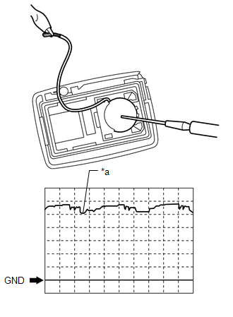
(2) Attach a lead wire (0.6 mm (0.0236 in.) or less in diameter including wire sheath) with tape or equivalent to the negative terminal.
NOTICE:
Do not wrap the lead wire around a terminal, wedge it between terminals, or solder it. A terminal may be deformed or damaged, and the battery will not be able to be installed correctly.
(3) Carefully extend the lead wire from the position shown in the illustration and install the previously removed transmitter battery.
|
(4) Using an oscilloscope, check the transmitter battery voltage waveform. HINT: When measuring the battery voltage, bring the electrical key transmitter
within the smart key system operating range and operate the lock switch
of a door handle to perform the measurement. For the smart key system operating
range, refer to System Description (See page
Standard Voltage:
If the result is not as specified, replace the transmitter battery. Text in Illustration
|
|
Installation
INSTALLATION
CAUTION / NOTICE / HINT
NOTICE:
Take extra care when handling these precision electronic components.
PROCEDURE
1. INSTALL TRANSMITTER BATTERY
|
(a) Install the battery (lithium battery: CR1632) with the positive (+) side facing upward as shown in the illustration. NOTICE:
|
|
.png)
(b) Install the transmitter housing cover.
(c) Insert the emergency key into the transmitter.
(d) Press one of the transmitter switches and check that the LED illuminates.
 Installation
INSTALLATION
PROCEDURE
1. INSTALL DOOR CONTROL SWITCH ASSEMBLY
(a) Attach the 2 claws to install the door control switch assembly.
(b) Con ...

Other materials about Toyota 4Runner:
Problem Symptoms Table
PROBLEM SYMPTOMS TABLE
HINT:
Use the table below to help determine the cause of problem symptoms.
If multiple suspected areas are listed, the potential causes of the symptoms
are listed in order of probability in the "Suspected Area" ...
Driver Side Power Window Auto Up / Down Function does not Operate with Power
Window Master Switch
DESCRIPTION
If the auto up/down function does not operate, the cause may be one or more of
the following:
The ECU in the power window regulator motor determines that the power
window regulator motor has not been initialized.
The master switc ...

0.0086