Toyota 4Runner: Door Courtesy Switch Circuit
DESCRIPTION
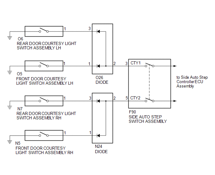
The side auto step controller ECU assembly receives the door open/closed signal from each door courtesy light switch via the side auto step switch assembly.
WIRING DIAGRAM
CAUTION / NOTICE / HINT
HINT:
Inspection should be performed on the door courtesy switch circuit on the side where the automatic running board is malfunctioning.
PROCEDURE
|
1. |
READ VALUE USING TECHSTREAM (DOOR COURTESY LIGHT SWITCH) |
(a) Using the Techstream, read the Data List (See page
.gif) ).
).
Main Body
|
Tester Display |
Measurement Item/Range |
Normal Condition |
Diagnostic Note |
|---|---|---|---|
|
RR Door Courtesy SW |
Rear door courtesy light switch RH signal / ON or OFF |
ON: Rear door RH open OFF: Rear door RH closed |
- |
|
RL Door Courtesy SW |
Rear door courtesy light switch LH signal / ON or OFF |
ON: Rear door LH open OFF: Rear door LH closed |
- |
|
FR Door Courtesy SW |
Front door courtesy light switch RH signal / ON or OFF |
ON: Front door RH closed OFF: Front door RH open |
- |
|
FL Door Courtesy SW |
Front door courtesy light switch LH signal / ON or OFF |
ON: Front door LH closed OFF: Front door LH open |
- |
OK:
Normal conditions listed above are displayed.
| NG | .gif) |
LIGHTING SYSTEM |
|
.gif)
|
2. |
CHECK HARNESS AND CONNECTOR (DOOR COURTESY LIGHT SWITCH - DIODE) |
(a) for LH
(1) Disconnect the O5 and O6 door courtesy light switch connectors.
(2) Disconnect the O26 diode connector.
(b) for RH
(1) Disconnect the N5 and N7 door courtesy light switch connectors.
(2) Disconnect the N24 diode connector.
(c) Measure the resistance according to the value(s) in the table below.
Standard Resistance (Check for Open):
for LH
|
Tester Connection |
Condition |
Specified Condition |
|---|---|---|
|
O5-1 - O26-1 |
Always |
Below 1 Ω |
|
O6-1 - O26-3 |
Always |
Below 1 Ω |
for RH
|
Tester Connection |
Condition |
Specified Condition |
|---|---|---|
|
N5-1 - N24-1 |
Always |
Below 1 Ω |
|
N7-1 - N24-3 |
Always |
Below 1 Ω |
Standard Resistance (Check for Short):
for LH
|
Tester Connection |
Condition |
Specified Condition |
|---|---|---|
|
O5-1 - Body ground |
Always |
10 kΩ or higher |
|
O6-1 - Body ground |
Always |
10 kΩ or higher |
for RH
|
Tester Connection |
Condition |
Specified Condition |
|---|---|---|
|
N5-1 - Body ground |
Always |
10 kΩ or higher |
|
N7-1 - Body ground |
Always |
10 kΩ or higher |
| NG | |
REPAIR OR REPLACE HARNESS OR CONNECTOR |
|
|
3. |
CHECK HARNESS AND CONNECTOR (DIODE - SIDE AUTO STEP SWITCH) |
(a) Disconnect the F90 side auto step switch assembly connector.
(b) Measure the resistance according to the value(s) in the table below.
Standard Resistance (Check for Open):
for LH
|
Tester Connection |
Condition |
Specified Condition |
|---|---|---|
|
O26-2 - F90-3 (CTY1) |
Always |
Below 1 Ω |
for RH
|
Tester Connection |
Condition |
Specified Condition |
|---|---|---|
|
N24-2 - F90-5 (CTY2) |
Always |
Below 1 Ω |
Standard Resistance (Check for Short):
for LH
|
Tester Connection |
Condition |
Specified Condition |
|---|---|---|
|
O26-2 - Body ground |
Always |
10 kΩ or higher |
for RH
|
Tester Connection |
Condition |
Specified Condition |
|---|---|---|
|
N24-2 - Body ground |
Always |
10 kΩ or higher |
| NG | |
REPAIR OR REPLACE HARNESS OR CONNECTOR |
|
|
4. |
REPLACE DIODE |
(a) Replace the diode on the malfunctioning side with a new or correctly functioning diode.
|
|
5. |
CHECK AUTOMATIC RUNNING BOARD OPERATION |
(a) Check that the automatic running board functions normally (See page
).
OK:
Malfunction disappears.
| OK | |
END |
| NG | |
PROCEED TO NEXT SUSPECTED AREA SHOWN IN PROBLEM SYMPTOMS TABLE |
 Side Auto Step Switch Circuit
DESCRIPTION
The side auto step controller ECU assembly receives the door open/closed signal
from each door courtesy light switch via the side auto step switch assembly.
WIRING DIAGRAM
CAUTION / ...
 Speed Signal Circuit
DESCRIPTION
The vehicle speed signal consists of pulses sent to the side auto step controller
ECU assembly from the main body ECU (multiplex network body ECU).
WIRING DIAGRAM
PROCEDURE
...
Other materials about Toyota 4Runner:
Short in Driver Side Squib Circuit (B1800/51-B1803/51)
DESCRIPTION
The driver side squib circuit consists of the center airbag sensor,
spiral cable and steering pad.
The circuit instructs the SRS to deploy when deployment conditions are
met.
These DTCs are stored when a malfunction is detec ...
Downhill Assist Control Indicator Light Remains ON
DESCRIPTION
When the downhill assist control switch is turned on, the downhill assist control
function is available and the downhill assist control indicator light illuminates.
WIRING DIAGRAM
Refer to Downhill Assist Control Indicator Light does not Come ...

0.0095