Toyota 4Runner: Downhill Assist Control Switch
Components
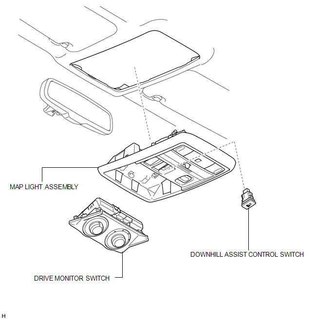
COMPONENTS
ILLUSTRATION
Removal
REMOVAL
PROCEDURE
1. REMOVE DRIVE MONITOR SWITCH
.gif)
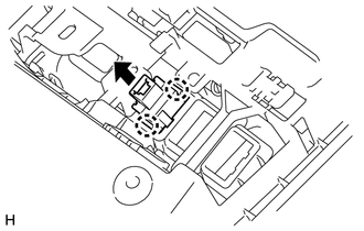
2. REMOVE MAP LIGHT ASSEMBLY
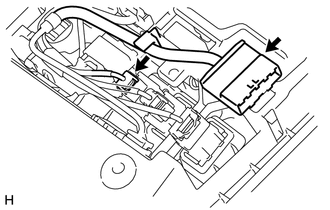
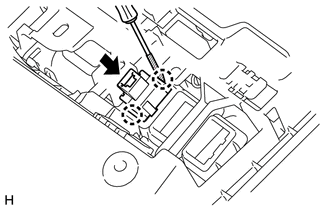
3. REMOVE DOWNHILL ASSIST CONTROL SWITCH
|
(a) Disconnect the 2 connectors. |
|
|
(b) Using a screwdriver, detach the 2 claws and remove the downhill assist control switch from the map light assembly. HINT: Tape the screwdriver tip before use. |
|
Inspection
INSPECTION
PROCEDURE
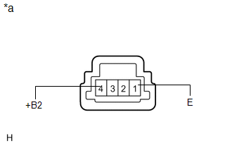
1. CHECK DOWNHILL ASSIST CONTROL SWITCH
|
(a) Measure the resistance according to the value(s) in the table below. Standard Resistance:
If the result is not as specified, replace the downhill assist control switch. |
|
Installation
INSTALLATION
PROCEDURE
1. INSTALL DOWNHILL ASSIST CONTROL SWITCH
|
(a) Attach the 2 claws to install the downhill assist control switch to the map lamp assembly. |
|
(b) Connect the 2 connectors.
2. INSTALL MAP LIGHT ASSEMBLY
.gif)
3. INSTALL DRIVE MONITOR SWITCH
4. PERFORM DOWNHILL ASSIST CONTROL CALIBRATION
(a) Perform downhill assist control switch calibration (See page
).
 Crawl Switch
Components
COMPONENTS
ILLUSTRATION
Removal
REMOVAL
PROCEDURE
1. REMOVE DRIVE MONITOR SWITCH (CRAWL CONTROL SWITCH AND MULTI-TERRAIN SELECT
SWITCH)
(a) Detach the 4 claws and ...
 Front Speed Sensor
Components
COMPONENTS
ILLUSTRATION
Removal
REMOVAL
CAUTION / NOTICE / HINT
HINT:
The procedure listed below is for the LH side.
Other than areas where instructions are provide ...
Other materials about Toyota 4Runner:
Reassembly
REASSEMBLY
PROCEDURE
1. INSTALL FRONT PROPELLER SHAFT UNIVERSAL JOINT SPIDER BEARING
HINT:
Use the same procedure for all propeller shaft universal joint spider bearing.
(a) Apply MP grease to a new spider and spider bearing.
NOTICE:
Be c ...
Data List / Active Test
DATA LIST / ACTIVE TEST
1. DATA LIST
HINT:
Using the Techstream to read the Data List allows the values or states of switches,
sensors, actuators and other items to be read without removing any parts. This non-intrusive
inspection can be very useful bec ...

0.0106