Toyota 4Runner: ECM Communication Stop Mode
DESCRIPTION
|
Detection Item |
Symptom |
Trouble Area |
|---|---|---|
|
ECM Communication Stop Mode |
Either condition is met:
|
|
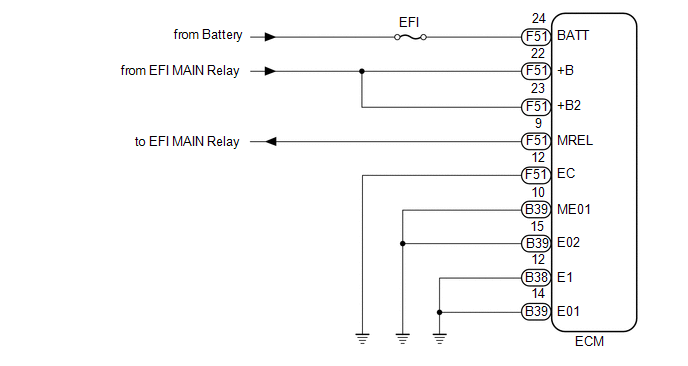
WIRING DIAGRAM
CAUTION / NOTICE / HINT
NOTICE:
Inspect the fuses for circuits related to this system before performing the following inspection procedure.
PROCEDURE
|
1. |
CHECK HARNESS AND CONNECTOR (ECM - BATTERY AND BODY GROUND) |
(a) Disconnect the B38, B39 and F51 ECM connectors.
.png) Text in Illustration
Text in Illustration
|
*a |
Front view of wire harness connector (to ECM) |
- |
- |
(b) Measure the resistance according to the value(s) in the table below.
Standard Resistance:
|
Tester Connection |
Condition |
Specified Condition |
|---|---|---|
|
B38-12 (E1) - Body ground |
Always |
Below 1 Ω |
|
B39-10 (ME01) - Body ground |
Always |
Below 1 Ω |
|
B39-14 (E01) - Body ground |
Always |
Below 1 Ω |
|
B39-15 (E02) - Body ground |
Always |
Below 1 Ω |
|
F51-12 (EC) - Body ground |
Always |
Below 1 Ω |
(c) Measure the voltage according to the value(s) in the table below.
Standard Voltage:
|
Tester Connection |
Condition |
Specified Condition |
|---|---|---|
|
F51-24 (BATT) - Body ground |
Always |
11 to 14 V |
|
F51-23 (+B2) - Body ground |
Battery positive (+) voltage applied to terminal F51-9 (MREL) |
11 to 14 V |
|
F51-22 (+B) - Body ground |
Battery positive (+) voltage applied to terminal F51-9 (MREL) |
11 to 14 V |
| OK | .gif) |
REPLACE ECM |
| NG | |
REPAIR OR REPLACE HARNESS OR CONNECTOR |
 Yaw Rate Sensor Communication Stop Mode
DESCRIPTION
Detection Item
Symptom
Trouble Area
Yaw Rate Sensor Communication Stop Mode
Either condition is met:
"Yaw R ...
 Main Body ECU Communication Stop Mode
DESCRIPTION
Detection Item
Symptom
Trouble Area
Main Body ECU Communication Stop Mode
Either condition is met:
"Main Bo ...
Other materials about Toyota 4Runner:
Front Passenger Side Power Window Switch
Components
COMPONENTS
ILLUSTRATION
Inspection
INSPECTION
PROCEDURE
1. INSPECT POWER WINDOW REGULATOR SWITCH ASSEMBLY
(a) Measure the resistance according to the value(s) in the table below.
Standard Resistance:
T ...
Horn System
Parts Location
PARTS LOCATION
ILLUSTRATION
Problem Symptoms Table
PROBLEM SYMPTOMS TABLE
HINT:
Use the table below to help determine the cause of problem symptoms. If multiple
suspected areas are listed, the potential causes of the symptoms are l ...

0.0269