Toyota 4Runner: ECU Power Source Circuit
DESCRIPTION
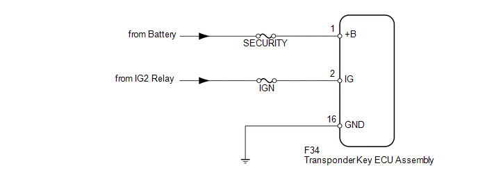
This circuit provides power to operate the transponder key ECU assembly.
WIRING DIAGRAM
CAUTION / NOTICE / HINT
NOTICE:
Inspect the fuses for circuits related to this system before performing the following inspection procedure.
PROCEDURE
|
1. |
CHECK HARNESS AND CONNECTOR (TRANSPONDER KEY ECU - BATTERY AND BODY GROUND) |
|
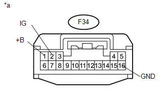
(a) Disconnect the F34 ECU connector. |
|
(b) Measure the voltage according to the value(s) in the table below.
Standard Voltage:
|
Tester Connection |
Switch Condition |
Specified Condition |
|---|---|---|
|
F34-1 (+B) - Body ground |
Always |
11 to 14 V |
|
F34-2 (IG) - Body ground |
Ignition switch off |
Below 1 V |
|
Ignition switch ON |
11 to 14 V |
(c) Measure the resistance according to the value(s) in the table below.
Standard Resistance:
|
Tester Connection |
Condition |
Specified Condition |
|---|---|---|
|
F34-16 (GND) - Body ground |
Always |
Below 1 Ω |
|
*a |
Front view of wire harness connector (to Transponder Key ECU Assembly) |
| OK | .gif) |
PROCEED TO NEXT SUSPECTED AREA SHOWN IN PROBLEM SYMPTOMS TABLE |
| NG | |
REPAIR OR REPLACE HARNESS OR CONNECTOR |
 Security Indicator Light Circuit
DESCRIPTION
When the engine immobiliser system is set, the security indicator light
blinks continuously, but does not illuminate if the engine immobiliser system
is not set.
WIR ...
 Id Code Box
Components
COMPONENTS
ILLUSTRATION
Installation
INSTALLATION
PROCEDURE
1. INSTALL ID CODE BOX
(a) Attach the 2 claws and move the ID code box in the direction of the
arrow. ...
Other materials about Toyota 4Runner:
Installation
INSTALLATION
PROCEDURE
1. INSTALL STEREO COMPONENT AMPLIFIER ASSEMBLY
(a) Install the stereo component amplifier to the No. 1 speaker assembly with
box with the 3 bolts.
2. INSTALL NO. 1 SPEAKER ASSEMBLY WITH BOX
(a) Attach the 2 claws, lower ...
Transmission Fluid Temperature Sensor "A" Circuit Low Input (P0712,P0713)
DESCRIPTION
Refer to DTC P0711 (See page
).
DTC Code
DTC Detection Condition
Trouble Area
P0712
ATF temperature sensor resistance is below 79 Ω for 0.5 sec. or more
(1-trip detection logic ...

0.0916