Toyota 4Runner: Engine Speed Signal Error (Test Mode DTC) (C2194/94)
DESCRIPTION
The tire pressure warning ECU receives an engine speed signal from the ECM. This DTC is stored upon entering test mode and cleared when an engine speed signal of 1000 rpm is detected for 3 seconds or more. This DTC is stored only in test mode.
|
DTC Code |
Detection Condition |
Trouble Area |
|---|---|---|
|
C2194/94 |
The test mode procedure is performed. |
|
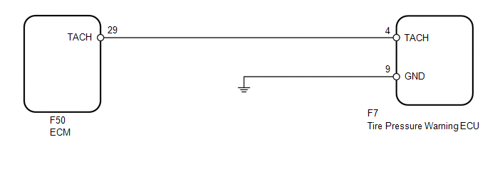
WIRING DIAGRAM
CAUTION / NOTICE / HINT
NOTICE:
- When replacing the tire pressure warning ECU, read the transmitter IDs stored in the old ECU using the Techstream and write them down before removal.
- It is necessary to perform registration of the transmitter IDs into
the tire pressure warning ECU after the ECU and/or the tire pressure warning
valve and transmitter has been replaced (See page
.gif) ).
).
PROCEDURE
|
1. |
READ VALUE USING TECHSTREAM (ENGINE SPEED) |
(a) Turn the ignition switch off.
(b) Connect the Techstream to the DLC3.
(c) Turn the ignition switch to ON.
(d) Turn the Techstream on.
(e) Enter the following menus: Chassis / Tire Pressure Monitor / Data List.
(f) Check that the values indicated on the Techstream and on the combination meter are the same.
Tire Pressure Monitor|
Tester Display |
Measurement Item/Range |
Normal Condition |
Diagnostic Note |
|---|---|---|---|
|
Engine Speed |
Engine speed/ min.: 0 rpm max.: 65535 rpm |
Almost same as actual engine speed |
The speed indicated on the combination meter. |
OK:
Engine speed indicated on the Techstream and on the combination meter are the same.
| OK | .gif) |
USE SIMULATION METHOD TO CHECK |
|
.gif)
|
2. |
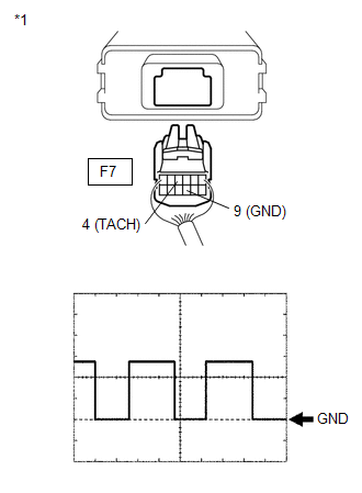
INSPECT TIRE PRESSURE WARNING ECU (TACH SIGNAL) |
(a) Disconnect the F7 ECU connector.
(b) Start the engine.
|
(c) Check the waveform of the ECU connector using an oscilloscope while idling the engine. OK:
HINT: The wavelength becomes shorter as the engine speed increases. Text in Illustration
|
|
| OK | |
REPLACE TIRE PRESSURE WARNING ECU |
|
|
3. |
CHECK HARNESS AND CONNECTOR (TIRE PRESSURE WARNING ECU - ECM) |
(a) Disconnect the F7 ECU connector.
(b) Disconnect the F50 ECM connector.
(c) Measure the resistance according to the value(s) in the table below.
Standard Resistance:
|
Tester Connection |
Condition |
Specified Condition |
|---|---|---|
|
F7-4 (TACH) - F50-29 (TACH) |
Always |
Below 1 Ω |
|
F7-4 (TACH) - Body ground |
Always |
10 kΩ or higher |
| OK | |
REPLACE ECM |
| NG | |
REPAIR OR REPLACE HARNESS OR CONNECTOR |
 Transmitter ID not Registered (C2171/71)
DESCRIPTION
The ID of each tire pressure warning valve and transmitter is registered to the
tire pressure warning ECU.
When the ECU detects that a transmitter ID code is not registered in the ECU, ...
 No Signal from Transmitter ID1 in Main Mode (C2121/21-C2125/25,C2181/81-C2185/85)
DESCRIPTION
The tire pressure warning valve and transmitters that are installed in the tire
and wheel assemblies measure the tire pressure of the tires. The measured values
are transmitted to the ...
Other materials about Toyota 4Runner:
Data List / Active Test
DATA LIST / ACTIVE TEST
1. READ DATA LIST
HINT:
Using the Techstream to read the Data List allows the values or states of switches,
sensors, actuators and other items to be read without removing any parts. This non-intrusive
inspection can be very usefu ...
On-vehicle Inspection
ON-VEHICLE INSPECTION
PROCEDURE
1. CHECK STEERING PAD (VEHICLE NOT INVOLVED IN COLLISION)
(a) Perform a diagnostic system check (See page
).
(b) With the steering pad installed on the vehicle, perform a visual check. If
there are any defects as mention ...

0.0284