Toyota 4Runner: Front Clearance Sonar Sensor RH Circuit
DESCRIPTION
The ultrasonic sensor sends and receives ultrasonic waves. Based on the received wave, the sensor calculates the approximate distance between the vehicle and the obstacle, and sends the distance value as a signal to the clearance warning ECU assembly.
WIRING DIAGRAM
PROCEDURE
|
1. |
REPLACE NO. 1 ULTRASONIC SENSOR (FRONT CORNER SENSOR RH) |
(a) Remove the No. 1 ultrasonic sensor (front corner sensor RH) (See page
.gif) ).
).
(b) Inspect the No. 1 ultrasonic sensor (front corner sensor RH) (See page
).
| NG | .gif) |
REPLACE NO. 1 ULTRASONIC SENSOR (FRONT CORNER SENSOR RH) |
|
.gif)
|
2. |
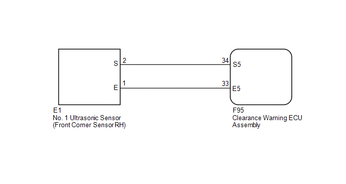
CHECK HARNESS AND CONNECTOR (FRONT CORNER SENSOR RH - CLEARANCE WARNING ECU ASSEMBLY) |
(a) Disconnect the E1 No. 1 ultrasonic sensor (front corner sensor RH) connector.
(b) Disconnect the F95 clearance warning ECU assembly connector.
(c) Measure the resistance according to the value(s) in the table below.
Standard Resistance:
|
Tester Connection |
Condition |
Specified Condition |
|---|---|---|
|
E1-1 (E) - F95-33 (E5) |
Always |
Below 1 Ω |
|
E1-2 (S) - F95-34 (S5) |
Always |
Below 1 Ω |
|
E1-1 (E) - Body ground |
Always |
10 kΩ or higher |
|
E1-2 (S) - Body ground |
Always |
10 kΩ or higher |
| OK | |
PROCEED TO NEXT SUSPECTED AREA SHOWN IN PROBLEM SYMPTOMS TABLE |
| NG | |
REPAIR OR REPLACE HARNESS OR CONNECTOR |
 Front Clearance Sonar Sensor LH Circuit
DESCRIPTION
The ultrasonic sensor sends and receives ultrasonic waves. Based on the received
wave, the sensor calculates the approximate distance between the vehicle and the
obstacle, and sends t ...
 Rear Clearance Sonar Sensor LH Circuit
DESCRIPTION
The ultrasonic sensor sends and receives ultrasonic waves. Based on the received
wave, the sensor calculates the approximate distance between the vehicle and the
obstacle, and sends t ...
Other materials about Toyota 4Runner:
Installation
INSTALLATION
PROCEDURE
1. INSTALL RACK AND PINION POWER STEERING GEAR ASSEMBLY
(a) Insert the power steering gear assembly into the vehicle in the order shown
in the illustration.
Install in this Direction (1)
In ...
Inspection
INSPECTION
PROCEDURE
1. INSPECT TIRES
(a) Check the tires for wear and proper inflation pressure.
Cold Tire Inflation Pressure (Unloaded Vehicle):
Tire Size
Vehicle Model
Front
kPa (kgf/cm2, psi)
Rear
kPa ...

0.0159