Toyota 4Runner: Fuel Receiver Gauge Malfunction
DESCRIPTION
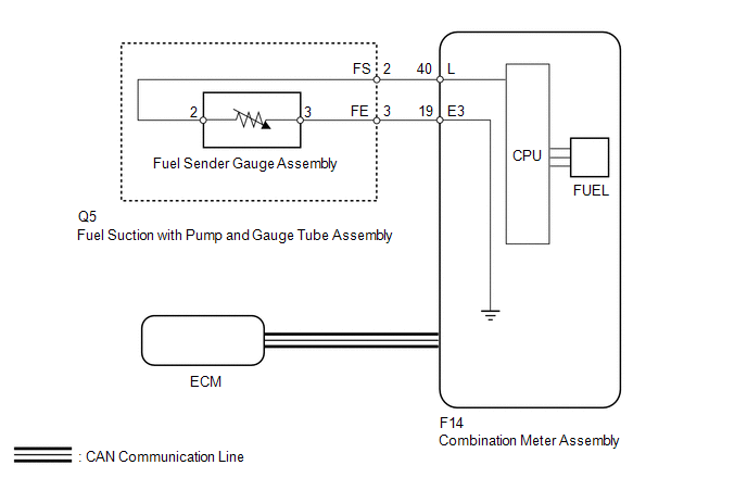
- The fuel sender gauge has a variable resistance mechanism. The resistance decreases when the fuel amount increases, and the resistance increases when the fuel amount decreases. The fuel receiver gauge changes based on the resistance of the fuel sender gauge.
NOTICE:
When the combination meter is removed or replaced, its connector is disconnected or fuel is added, the fuel receiver gauge display will return to normal within a maximum of 16 minutes after the ignition switch is turned to ON or when vehicle speed is input.
WIRING DIAGRAM
PROCEDURE
|
1. |
CHECK CAN COMMUNICATION SYSTEM |
(a) Check if a CAN communication DTC is output (See page
.gif) ).
).
Result
|
Result |
Proceed to |
|---|---|
|
CAN communication DTC is not output |
A |
|
CAN communication DTC is output |
B |
| B | .gif) |
GO TO CAN COMMUNICATION SYSTEM |
|
.gif)
|
2. |
PERFORM ACTIVE TEST USING TECHSTREAM (FUEL METER OPERATION) |
(a) Use the Active Test to check the operation of the fuel receiver gauge (See
page ).
Combination Meter
|
Tester Display |
Test Part |
Control Range |
Diagnostic Note |
|---|---|---|---|
|
Fuel Meter Operation |
Fuel receiver gauge |
Empty, 1/2, Full |
Confirm that the vehicle is stopped with the engine idling. |
OK:
Fuel receiver gauge indication is normal.
| NG | |
REPLACE COMBINATION METER ASSEMBLY |
|
|
3. |
READ VALUE USING TECHSTREAM (FUEL INPUT) |
(a) Use the Data List to check if the fuel receiver gauge is operating properly
(See page ).
Combination Meter
|
Tester Display |
Measurement Item/Range |
Normal Condition |
Diagnostic Note |
|---|---|---|---|
|
Fuel Input |
Fuel input signal/Min.: 0, Max.: 127.5 |
Current fuel level displayed |
Unit: Liters |
OK:
Fuel level signal displayed on the Techstream is almost the same as fuel receiver gauge indication.
| NG | |
REPLACE COMBINATION METER ASSEMBLY |
|
|
4. |
CHECK HARNESS AND CONNECTOR (COMBINATION METER - FUEL SUCTION WITH PUMP AND BODY GROUND) |
(a) Disconnect the F14 meter connector.
(b) Disconnect the Q5 gauge connector.
(c) Measure the resistance according to the value(s) in the table below.
Standard Resistance:
|
Tester Connection |
Condition |
Specified Condition |
|---|---|---|
|
F14-40 (L) - Q5-2 (FS) |
Always |
Below 1 Ω |
|
F14-19 (E3) - Q5-3 (FE) |
Always |
Below 1 Ω |
|
F14-40 (L) - Body ground |
Always |
10 kΩ or higher |
|
F14-19 (E3) - Body ground |
Always |
10 kΩ or higher |
| NG | |
REPAIR OR REPLACE HARNESS OR CONNECTOR |
|
|
5. |
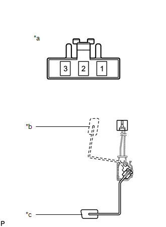
INSPECT FUEL SUCTION WITH PUMP AND GAUGE TUBE ASSEMBLY |
.png)
(a) Remove the fuel suction with pump and gauge tube assembly (See page
).
(b) Measure the resistance according to the value(s) in the table below.
Standard Resistance:
|
Tester Connection |
Condition |
Specified Condition |
|---|---|---|
|
A-2 (FS) - B-2 |
Always |
Below 1 Ω |
|
A-3 (FE) - B-3 |
|
*a |
Front view of wire harness connector (to Fuel Sender Gauge Assembly) |
|
*b |
Lower Side (to Fuel Sender Gauge Assembly) |
|
*c |
Connector A |
|
*d |
Connector B |
| NG | |
REPLACE FUEL SUCTION WITH PUMP AND GAUGE TUBE ASSEMBLY |
|
|
6. |
INSPECT FUEL SENDER GAUGE ASSEMBLY |
|
(a) Remove the fuel sender gauge assembly (See page
|
|
(b) Measure the resistance according to the value(s) in the table below.
Standard Resistance:
|
Tester Connection |
Condition |
Specified Condition |
|---|---|---|
|
2 - 3 |
Float level F (upper) |
12 to 18 Ω |
|
Float level E (lower) |
405 to 415 Ω |
|
*a |
Front view of wire harness connector (to Fuel Sender Gauge Assembly) |
|
*b |
Float level F (upper) |
|
*c |
Float level E (lower) |
| OK | |
REPLACE COMBINATION METER ASSEMBLY |
| NG | |
REPLACE FUEL SENDER GAUGE ASSEMBLY |
 Speedometer Malfunction
DESCRIPTION
The combination meter receives vehicle speed signals from the skid control ECU
via the CAN communication line. The wheel speed sensors output voltages that vary
according to the vehic ...
 Tachometer Malfunction
DESCRIPTION
In this circuit, the meter CPU receives engine speed signals from the ECM using
the CAN communication system. The meter CPU displays the engine speed, which is
calculated based on the ...
Other materials about Toyota 4Runner:
Terminals Of Ecu
TERMINALS OF ECU
1. CHECK COMBINATION METER ASSEMBLY
(a) Disconnect the F14 combination meter assembly connector.
(b) Measure the resistance and voltage according to the value(s) in the table
below.
Terminal No. (Symbol)
Wiring Co ...
Problem Symptoms Table
PROBLEM SYMPTOMS TABLE
HINT:
Use the table below to help determine the cause of problem symptoms. If multiple
suspected areas are listed, the potential causes of the symptoms are listed in order
of probability in the "Suspected Area" column of ...

0.0264