Toyota 4Runner: Hazard Warning Switch
Components
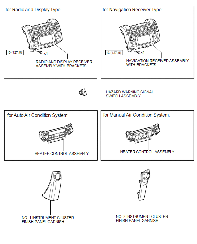
COMPONENTS
ILLUSTRATION
Removal
REMOVAL
PROCEDURE
1. REMOVE NO. 1 INSTRUMENT CLUSTER FINISH PANEL GARNISH
.gif)
2. REMOVE NO. 2 INSTRUMENT CLUSTER FINISH PANEL GARNISH
3. REMOVE HEATER CONTROL ASSEMBLY
4. REMOVE RADIO AND DISPLAY RECEIVER ASSEMBLY WITH BRACKETS (for Radio and Display Type)
5. REMOVE NAVIGATION RECEIVER ASSEMBLY WITH BRACKETS (for Navigation Receiver Type)
6. REMOVE HAZARD WARNING SIGNAL SWITCH ASSEMBLY
|
(a) Disconnect the connector. |
|
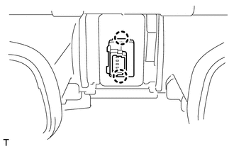
(b) Detach the 2 claws to remove the hazard warning signal switch assembly.
Inspection
INSPECTION
PROCEDURE
1. INSPECT HAZARD WARNING SIGNAL SWITCH ASSEMBLY
|
(a) Measure the resistance according to the value(s) in the table below. Standard Resistance:
|
|
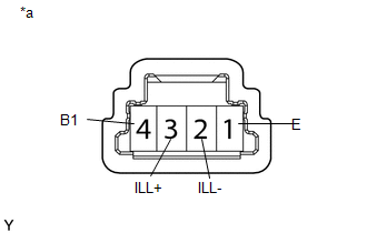
(b) Apply battery voltage to the connector and check the LED illumination condition.
OK:
|
Measurement Condition |
Specified Condition |
|---|---|
|
Battery positive (+) → Terminal 3 (ILL+) Battery negative (-) → Terminal 2 (ILL-) |
LED illuminates |
If the result is not as specified, there may be a malfunction in the hazard warning signal switch.
Text in Illustration|
*a |
Component without harness connected (Hazard Warning Signal Switch Assembly) |
Installation
INSTALLATION
PROCEDURE
1. INSTALL HAZARD WARNING SIGNAL SWITCH ASSEMBLY
(a) Attach the 2 claws to install the hazard warning signal switch assembly.
(b) Connect the connector.
2. INSTALL RADIO AND DISPLAY RECEIVER ASSEMBLY WITH BRACKETS (for Radio and Display Type)
.gif)
3. INSTALL NAVIGATION RECEIVER ASSEMBLY WITH BRACKETS (for Navigation Receiver Type)
4. INSTALL HEATER CONTROL ASSEMBLY
5. INSTALL NO. 1 INSTRUMENT CLUSTER FINISH PANEL GARNISH
6. INSTALL NO. 2 INSTRUMENT CLUSTER FINISH PANEL GARNISH
 Installation
INSTALLATION
CAUTION / NOTICE / HINT
HINT:
Use the same procedure for both the RH and LH sides.
The procedure listed below is for the LH side.
PROCEDURE
1. INSTALL FOG LIGHT ASS ...

Other materials about Toyota 4Runner:
Reverse Signal Circuit
DESCRIPTION
The navigation receiver assembly receives a reverse signal from the park/neutral
position switch assembly.
WIRING DIAGRAM
CAUTION / NOTICE / HINT
NOTICE:
After replacing the navigation receiver assembly of vehicles subscribed
t ...
Disassembly
DISASSEMBLY
PROCEDURE
1. REMOVE FRONT NO. 1 LOWER ARM BUSH LH
(a) Using a chisel and hammer, pry the flange of the bush outward.
(b) Using SST and a press, press out the bush.
SST: 09632-36 ...

0.0089