Toyota 4Runner: Horn
Components
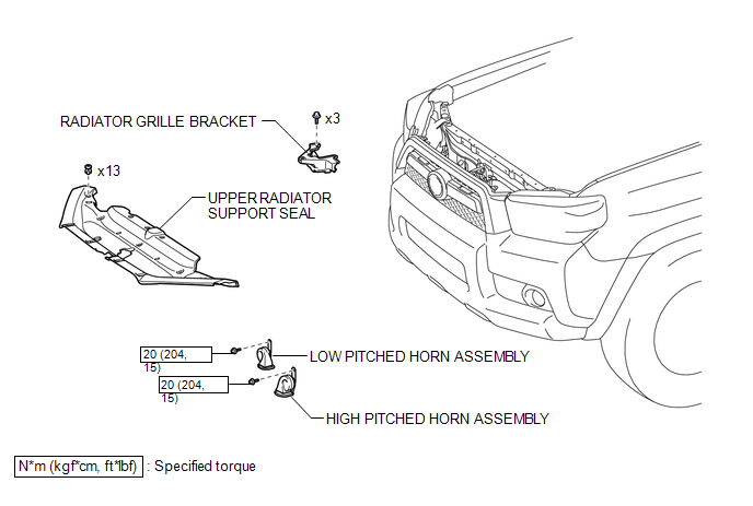
COMPONENTS
ILLUSTRATION
Inspection
INSPECTION
PROCEDURE
1. INSPECT HIGH PITCHED HORN ASSEMBLY
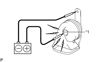
(a) Apply battery voltage and check the operation of the horn according to the table below.
OK:
|
Measurement Condition |
Specified Condition |
|---|---|
|
Battery positive (+) → Terminal 1 Battery negative (-) → Body ground |
High pitched horn sounds |
If the result is not as specified, replace the high pitched horn assembly.
Text in Illustration|
*1 |
Terminal 1 |
2. INSPECT LOW PITCHED HORN ASSEMBLY
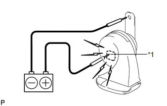
(a) Apply battery voltage and check the operation of the horn according to the table below.
OK:
|
Measurement Condition |
Specified Condition |
|---|---|
|
Battery positive (+) → Terminal 1 Battery negative (-) → Body ground |
Low pitched horn sounds |
If the result is not as specified, replace the low pitched horn assembly.
Text in Illustration|
*1 |
Terminal 1 |
Removal
REMOVAL
PROCEDURE
1. REMOVE UPPER RADIATOR SUPPORT SEAL
.gif)
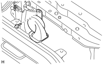
2. REMOVE HIGH PITCHED HORN ASSEMBLY
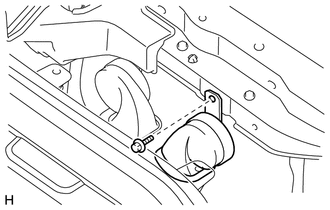
(a) Disconnect the connector.
(b) Remove the bolt and high pitched horn assembly.
3. REMOVE RADIATOR GRILLE BRACKET
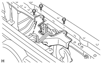
(a) Remove the 3 bolts and radiator grille bracket.
4. REMOVE LOW PITCHED HORN ASSEMBLY
(a) Disconnect the connector.
(b) Remove the bolt and low pitched horn assembly.
Installation
INSTALLATION
PROCEDURE
1. INSTALL LOW PITCHED HORN ASSEMBLY
(a) Install the low pitched horn assembly with the bolt.
Torque:
20 N·m {204 kgf·cm, 15 ft·lbf}
(b) Connect the connector.
2. INSTALL RADIATOR GRILLE BRACKET
(a) Install the radiator grille bracket with the 3 bolts.
3. INSTALL HIGH PITCHED HORN ASSEMBLY
(a) Install the high pitched horn assembly with the bolt.
Torque:
20 N·m {204 kgf·cm, 15 ft·lbf}
(b) Connect the connector.
4. INSTALL UPPER RADIATOR SUPPORT SEAL
.gif)
 Horn
Horn
...
 Horn System
Parts Location
PARTS LOCATION
ILLUSTRATION
Problem Symptoms Table
PROBLEM SYMPTOMS TABLE
HINT:
Use the table below to help determine the cause of problem symptoms. If multiple
suspected ...
Other materials about Toyota 4Runner:
Generator Signal Circuit
DESCRIPTION
When the engine is started, the generator assembly turns on and a voltage pulse
signal is generated.
This signal is used by the air conditioning amplifier assembly.
The signal expressing the amount of output from the generator assembly is one ...
Mute Signal Circuit between Stereo Component Amplifier and Telematics Transceiver
DESCRIPTION
The DCM (telematics transceiver) sends a mute signal to the stereo component
amplifier assembly.
The stereo component amplifier assembly controls the volume according to the
mute signal from the DCM (telematics transceiver).
WIRING DIAGRAM
...

0.0239