Toyota 4Runner: ID Code Box Power Source Circuit
DESCRIPTION
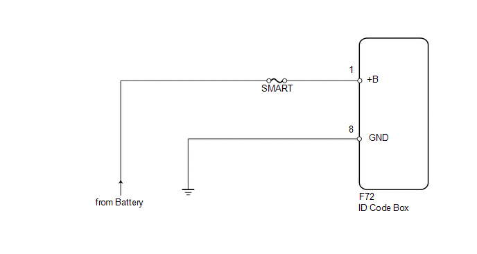
This circuit provides power to operate the ID code box.
WIRING DIAGRAM
CAUTION / NOTICE / HINT
NOTICE:
Inspect the fuses for circuits related to this system before performing the following inspection procedure.
PROCEDURE
|
1. |
CHECK HARNESS AND CONNECTOR (ID CODE BOX - BATTERY AND BODY GROUND) |
|
(a) Disconnect the F72 box connector. |
|
.png)
(b) Measure the voltage according to the value(s) in the table below.
Standard Voltage:
|
Tester Connection |
Condition |
Specified Condition |
|---|---|---|
|
F72-1 (+B) - Body ground |
Always |
11 to 14 V |
(c) Measure the resistance according to the value(s) in the table below.
Standard Resistance:
|
Tester Connection |
Condition |
Specified Condition |
|---|---|---|
|
F72-8 (GND) - Body ground |
Always |
Below 1 Ω |
|
*a |
Front view of wire harness connector (to ID Code Box) |
| OK | .gif) |
PROCEED TO NEXT SUSPECTED AREA SHOWN IN PROBLEM SYMPTOMS TABLE |
| NG | |
REPAIR OR REPLACE HARNESS OR CONNECTOR |
 Certification ECU Power Source Circuit
DESCRIPTION
This circuit provides power to the certification ECU.
WIRING DIAGRAM
CAUTION / NOTICE / HINT
NOTICE:
Inspect the fuses for circuits related to this system before performing the foll ...
 Security Indicator Light Circuit
DESCRIPTION
When the engine immobiliser system is set, the security indicator flashes
continuously, but does not illuminate if the engine immobiliser system is
not set.
WIRING D ...
Other materials about Toyota 4Runner:
Removal
REMOVAL
CAUTION / NOTICE / HINT
HINT:
Use the same procedure for the RH and LH sides.
The procedure listed below is for the LH side.
When removing the window frame moulding, black out tape and outside
stripe, heat the vehicle body, windo ...
Reassembly
REASSEMBLY
CAUTION / NOTICE / HINT
CAUTION:
Wear protective gloves. Sharp areas on the parts may injure your hands.
HINT:
Use the same procedure for the RH and LH sides.
The procedure listed below is for the LH side.
PROCEDURE
1. INSTA ...

0.0251