Toyota 4Runner: IG Signal Circuit
DESCRIPTION
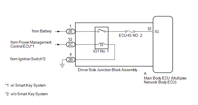
This circuit detects the ignition switch ON or off condition, and sends it to the main body ECU.
WIRING DIAGRAM
CAUTION / NOTICE / HINT
NOTICE:
Inspect the fuses for circuits related to this system before performing the following inspection procedure.
PROCEDURE
|
1. |
READ VALUE USING TECHSTREAM (IGNITION SWITCH) |
(a) Using the Techstream, read the Data List (See page
.gif) ).
).
Main Body
|
Tester Display |
Measurement Item/Range |
Normal Condition |
Diagnostic Note |
|---|---|---|---|
|
IG SW |
Ignition switch ON signal / ON or OFF |
ON: Ignition switch ON OFF: Ignition switch off |
- |
OK:
Normal conditions listed above are displayed.
| OK | .gif) |
PROCEED TO NEXT SUSPECTED AREA SHOWN IN PROBLEM SYMPTOMS TABLE |
|
.gif)
|
2. |
CHECK HARNESS AND CONNECTOR (BATTERY - MAIN BODY ECU) |
|
(a) Remove the main body ECU (See page
|
|
(b) Measure the voltage according to the value(s) in the table below.
Standard Voltage:
|
Tester Connection |
Switch Condition |
Specified Condition |
|---|---|---|
|
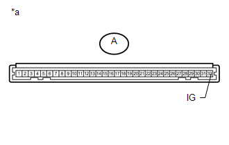
A-32 (IG) - Body ground |
Ignition switch ON |
11 to 14 V |
|
*a |
Front view of wire harness connector (to Main Body ECU) |
| OK | |
REPLACE MAIN BODY ECU (MULTIPLEX NETWORK BODY ECU) |
| NG | |
REPAIR OR REPLACE HARNESS OR CONNECTOR |
 ACC Signal Circuit
DESCRIPTION
This circuit detects the ignition switch ACC or off condition, and sends it to
the main body ECU.
WIRING DIAGRAM
CAUTION / NOTICE / HINT
NOTICE:
Inspect the fuses for circuits rel ...
 Back Door Courtesy Switch Circuit
DESCRIPTION
The multiplex network door ECU receives a back door open/closed signal from the
back door lock.
WIRING DIAGRAM
PROCEDURE
1.
READ VALUE USING TECHSTREAM (BACK ...
Other materials about Toyota 4Runner:
Shift Solenoid "E" Control Circuit Low (Shift Solenoid Valve SR) (P0985,P0986)
DESCRIPTION
Shifting from 1st to 5th is performed in combination with the ON and OFF operation
of the shift solenoid valves SL1, SL2, S1, S2 and SR, which is controlled by the
ECM. If an open or short circuit occurs in one of the shift solenoid valves, th ...
Precaution
PRECAUTION
1. IGNITION SWITCH EXPRESSION
HINT:
The type of ignition switch used on this model differs according to the specifications
of the vehicle. The expressions listed in the table below are used in this section.
Expression
Ign ...

0.0075