Toyota 4Runner: Ignition Key Cylinder Light
Components
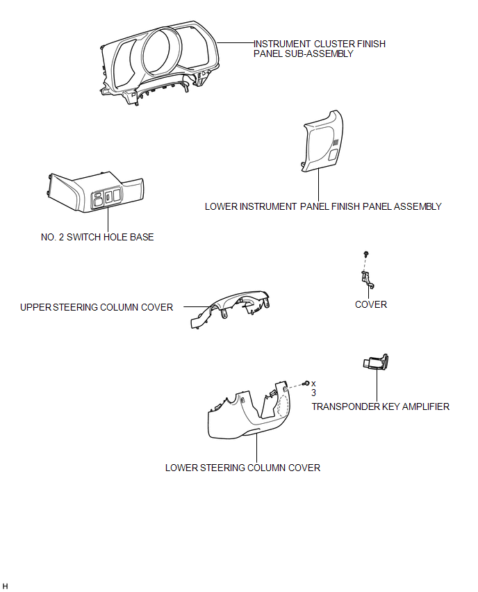
COMPONENTS
ILLUSTRATION
Removal
REMOVAL
PROCEDURE
1. REMOVE NO. 2 SWITCH HOLE BASE
.gif)
2. REMOVE LOWER INSTRUMENT PANEL FINISH PANEL ASSEMBLY
3. REMOVE INSTRUMENT CLUSTER FINISH PANEL SUB-ASSEMBLY
4. REMOVE LOWER STEERING COLUMN COVER
5. REMOVE UPPER STEERING COLUMN COVER
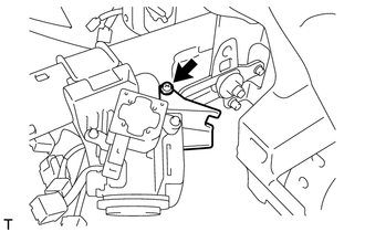
6. REMOVE TRANSPONDER KEY AMPLIFIER
|
(a) Remove the screw and cover. |
|
|
(b) Turn the key amplifier as shown in the illustration to detach the 2 claws and remove the key amplifier. |
|
(c) Disconnect the connector.
Inspection
INSPECTION
PROCEDURE
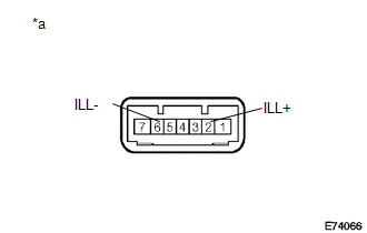
1. INSPECT TRANSPONDER KEY AMPLIFIER
|
(a) Apply battery voltage to the connector and check the LED illumination. OK:
If the result is not as specified, replace the transponder key amplifier. Text in Illustration
|
|
Installation
INSTALLATION
PROCEDURE
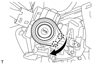
1. INSTALL TRANSPONDER KEY AMPLIFIER
|
(a) Connect the connector. |
|
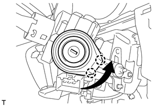
(b) Turn the key amplifier as shown in the illustration to attach the 2 claws and install the key amplifier.
(c) Install the cover with the screw.
2. INSTALL UPPER STEERING COLUMN COVER
.gif)
3. INSTALL LOWER STEERING COLUMN COVER
4. INSTALL INSTRUMENT CLUSTER FINISH PANEL SUB-ASSEMBLY
5. INSTALL LOWER INSTRUMENT PANEL FINISH PANEL ASSEMBLY
6. INSTALL NO. 2 SWITCH HOLE BASE
 Front Door Courtesy Switch
Components
COMPONENTS
ILLUSTRATION
Inspection
INSPECTION
PROCEDURE
1. INSPECT FRONT DOOR COURTESY LIGHT SWITCH ASSEMBLY
(a) Measure the resistance according to the value(s) in ...
 Lighting System
...
Other materials about Toyota 4Runner:
Installation
INSTALLATION
PROCEDURE
1. INSTALL RACK AND PINION POWER STEERING GEAR ASSEMBLY
(a) Insert the power steering gear assembly into the vehicle in the order shown
in the illustration.
Install in this Direction (1)
In ...
AVC-LAN Circuit
DESCRIPTION
Each unit of the navigation system connected to the AVC-LAN (communication bus)
transfers the switch signals using the AVC-LAN.
If a short to +B or short to ground occurs in the AVC-LAN, the navigation system
will not function normally becaus ...

0.0071