Toyota 4Runner: Illumination for Panel Switch does not Come on with Tail Switch ON
PROCEDURE
|
1. |
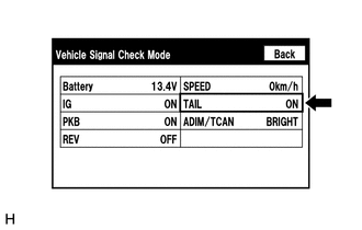
CHECK VEHICLE SIGNAL (OPERATION CHECK) |
(a) Enter the "Vehicle Signal Check Mode" screen. Refer to Check Vehicle Signal
in Operation Check (See page .gif) ).
).

(b) Check that the display changes between ON and OFF according to the light control switch operation.
OK:
|
Light Control Switch |
Display |
|---|---|
|
Tail or head |
ON |
|
Off |
OFF |
HINT:
This display is updated once per second. As a result, it is normal for the display to lag behind the actual switch operation.
| OK | .gif) |
REPLACE RADIO AND DISPLAY RECEIVER ASSEMBLY |
| NG | .gif) |
PROCEED TO NEXT SUSPECTED AREA SHOWN IN PROBLEM SYMPTOMS TABLE |
 Radio Broadcast cannot be Received or Poor Reception
PROCEDURE
1.
CHECK RADIO AND DISPLAY RECEIVER ASSEMBLY
(a) Check the radio automatic station search function.
(1) Check the radio automatic station search function b ...
 Display does not Dim when Light Control Switch is Turned ON
PROCEDURE
1.
CHECK IMAGE QUALITY SETTING
(a) Turn the light control switch to the tail or head position.
(b) Check that the daytime screen setting on the display adj ...
Other materials about Toyota 4Runner:
Pressure Control Solenoid "D" Performance (Shift Solenoid Valve SLT) (P2714)
DESCRIPTION
The linear solenoid valve (SLT) controls the transmission line pressure for smooth
transmission operation based on signals from the throttle position sensor and vehicle
speed sensor. The ECM adjusts the duty ratio* of the SLT solenoid valve ...
Vehicle Speed Signal Circuit between Radio Receiver and Combination Meter
DESCRIPTION
for Automatic Sound Levelizer (ASL):
This circuit is necessary for the Automatic Sound Levelizer (ASL) built
into the radio and display receiver assembly.
The Automatic Sound Levelizer (ASL) function automatically adjusts the
a ...
0.0268
