Toyota 4Runner: Inspection
INSPECTION
PROCEDURE
1. INSPECT VANE PUMP SHAFT AND BUSH IN VANE PUMP FRONT HOUSING
|
(a) Using a micrometer, measure the outer diameter of the vane pump shaft. Text in Illustration
|
|
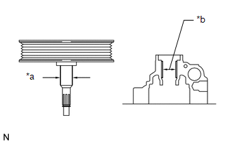
(b) Using a vernier caliper, measure the inner diameter of the vane pump front housing bush.
(c) Calculate the oil clearance.
Oil clearance = Inner diameter of the bush - Outer diameter of the shaft
Maximum oil clearance:
0.07 mm (0.00276 in.)
If the oil clearance is more than the maximum, replace the vane pump assembly.
2. INSPECT VANE PUMP ROTOR AND VANE PUMP PLATE
|
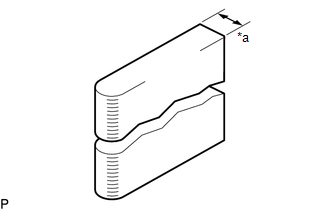
(a) Using a micrometer, measure the thickness of the vane pump plates. Standard thickness: 1.405 to 1.411 mm (0.0554 to 0.0555 in.) Text in Illustration
If the thickness is not as specified, replace the vane pump assembly. |
|
|
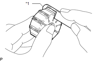
(b) Using a feeler gauge, measure the clearance between the side face of the vane pump rotor groove and the vane pump plate. Maximum clearance: 0.025 mm (0.00098 in.) Text in Illustration
If the clearance is more than the maximum, replace the vane pump assembly. |
|
3. INSPECT PRESSURE PORT UNION
If the union seat in the pressure port union is severely damaged, it may cause fluid leakage. In that case, replace the vane pump assembly.
 Disassembly
DISASSEMBLY
PROCEDURE
1. SECURE VANE PUMP ASSEMBLY
(a) Using SST, secure the vane pump in a vise.
SST: 09630-00014
09631-00132
2. RE ...
 Reassembly
REASSEMBLY
CAUTION / NOTICE / HINT
NOTICE:
When installing parts, coat the parts indicated by arrows with power steering
fluid (See page ).
PROCEDURE
1. INSTALL VANE PUMP HOUSING OIL SEAL
(a) ...
Other materials about Toyota 4Runner:
Electronic Circuit Inspection Procedure
ELECTRONIC CIRCUIT INSPECTION PROCEDURE
1. BASIC INSPECTION
(a) WHEN MEASURING RESISTANCE OF ELECTRONIC PARTS
(1) Unless otherwise stated, all resistance measurements should be made at an
ambient temperature of 20°C (68°F). Resistance measurements may b ...
Inspection
INSPECTION
PROCEDURE
1. INSPECT SEAT HEATER SWITCH LH
(a) Measure the resistance according to the value(s) in the table below.
Standard Resistance:
Tester Connection
Switch Condition
Specified Condition
...

0.007