Toyota 4Runner: Installation
INSTALLATION
CAUTION / NOTICE / HINT
HINT:
- Use the same procedure for the RH and LH sides.
- The procedure listed below is for the LH side.
- A bolt without a torque specification is shown in the standard bolt
chart (See page
.gif) ).
).
PROCEDURE
1. TEMPORARILY INSTALL FRONT SUSPENSION UPPER ARM ASSEMBLY LH
|
(a) Temporarily install the suspension upper arm and 2 washers with the bolt and nut. HINT: After stabilizing the suspension, tighten the nut. |
|
.png)
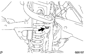
(b) Connect the bracket with the bolt.
Torque:
8.0 N·m {82 kgf·cm, 71 in·lbf}
|
(c) Install a new nut and clip. Torque: 110 N·m {1122 kgf·cm, 81 ft·lbf} |
|
2. INSTALL SKID CONTROL SENSOR WIRE
3. INSTALL FRONT WHEEL
Torque:
for aluminum wheel :
103 N·m {1050 kgf·cm, 76 ft·lbf}
for steel wheel :
112 N·m {1142 kgf·cm, 83 ft·lbf}
4. STABILIZE SUSPENSION
5. TIGHTEN FRONT SUSPENSION UPPER ARM ASSEMBLY LH
|
(a) Tighten the nut. Torque: 115 N·m {1173 kgf·cm, 85 ft·lbf} |
|

6. INSPECT AND ADJUST FRONT WHEEL ALIGNMENT
(a) Inspect and adjust the front wheel alignment (See page
).
 Reassembly
REASSEMBLY
PROCEDURE
1. INSTALL FRONT UPPER BALL JOINT DUST COVER LH
(a) Pack the upper arm ball joint with MP grease.
Grease capacity:
8.0 g (0.282 oz.)
Text in Illustration
...
 Rear Suspension
...
Other materials about Toyota 4Runner:
Removal
REMOVAL
CAUTION / NOTICE / HINT
HINT:
Use the same procedure for both the RH and LH sides.
The procedure listed below is for the LH side.
PROCEDURE
1. REMOVE UPPER RADIATOR SUPPORT SEAL
2. REMOVE FRONT FENDER MAIN SEAL LH
3. REMO ...
System Description
SYSTEM DESCRIPTION
1. DESCRIPTION OF SYSTEM
(a) When the tire pressure warning system detects that the tire pressure of a
tire is below the threshold, it illuminates the tire pressure warning light to warn
the driver.
(b) The tire pressure warning anten ...

0.0089