Toyota 4Runner: Installation
INSTALLATION
PROCEDURE
1. INSTALL REAR STABILIZER LINK ASSEMBLY
(a) Install the rear stabilizer link assembly with the bolt and nut.
Torque:
100 N·m {1020 kgf·cm, 74 ft·lbf}
HINT:
Turn the nut while holding the bolt.
2. INSTALL REAR STABILIZER CONTROL CYLINDER
(a) Install the 2 bleeder plug caps to the rear stabilizer control cylinder.
(b) Install the rear stabilizer control cylinder with the bolt and nut.
Torque:
100 N·m {1020 kgf·cm, 74 ft·lbf}
HINT:
Turn the nut while holding the bolt.
NOTICE:
Do not hold the rear stabilizer control cylinder by the cylinder boot.
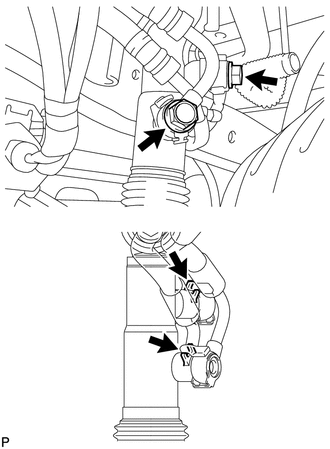
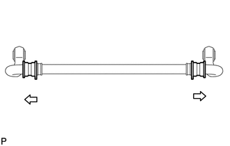
3. CONNECT REAR STABILIZER CONTROL TUBE ASSEMBLY
|
(a) Connect the rear stabilizer control tube to the rear stabilizer control cylinder with the 2 union bolts and 2 new pressure port gaskets. Torque: 69 N·m {704 kgf·cm, 51 ft·lbf} NOTICE: Insert the stoppers of the rear stabilizer control tube into the rear stabilizer control cylinder. |
|
4. TEMPORARILY INSTALL REAR STABILIZER BAR SUB-ASSEMBLY
(a) Install the 2 rear stabilizer bushes to the rear stabilizer bar.
HINT:
Install the stabilizer bush to the outer side of the stabilizer bush stopper on the stabilizer bar.
Text in Illustration
.png) |
Outer Side |
(b) Temporarily install the rear stabilizer bar with the 2 bolts and nuts.
5. INSTALL REAR STABILIZER LOWER BRACKET
|
(a) Support the rear stabilizer bar with a jack. NOTICE: Place a wooden block between the jack and rear stabilizer bar to prevent damage. |
|
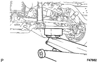
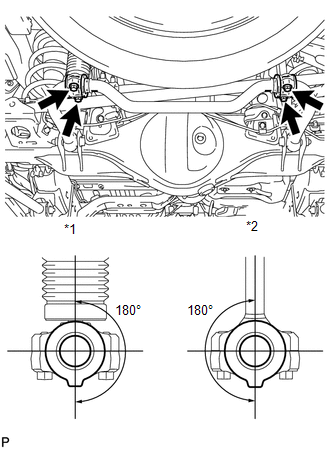
|
(b) Install the rear stabilizer bar and 2 rear stabilizer lower brackets with the 4 bolts. Torque: 45 N·m {459 kgf·cm, 33 ft·lbf} Text in Illustration
(1) Check that the protrusions on the rear stabilizer bush are positioned within 180° of the rear stabilizer control cylinder and rear stabilizer link. |
|
6. BLEED SUSPENSION FLUID
(a) Bleed the suspension fluid (See page .gif) ).
).
7. STABILIZE SUSPENSION
8. TIGHTEN REAR STABILIZER BAR SUB-ASSEMBLY
(a) Tighten the 2 bolts and 2 nuts.
Torque:
110 N·m {1122 kgf·cm, 81 ft·lbf}
HINT:
Turn the bolt while holding the nut.
9. INSTALL STABILIZER CONTROL VALVE PROTECTOR
10. INSTALL SIDE STEP ASSEMBLY LH
11. MEASURE VEHICLE HEIGHT
(a) Measure the vehicle height (See page ).
 Removal
REMOVAL
PROCEDURE
1. REMOVE SIDE STEP ASSEMBLY LH
2. REMOVE STABILIZER CONTROL VALVE PROTECTOR
3. DRAIN SUSPENSION FLUID
4. REMOVE REAR STABILIZER LOWER BRACKET
(a) Remove th ...
 Rear Stabilizer Bar(w/o Kdss)
Components
COMPONENTS
ILLUSTRATION
Inspection
INSPECTION
PROCEDURE
1. INSPECT REAR STABILIZER LINK ASSEMBLY
(a) As shown in the illustration, flip the ball joint stud back and ...
Other materials about Toyota 4Runner:
AVC-LAN Circuit
DESCRIPTION
Each unit of the navigation system connected to the AVC-LAN (communication bus)
transfers the switch signals using the AVC-LAN.
If a short to +B or short to ground occurs in the AVC-LAN, the navigation system
will not function normally becaus ...
TS and CG Terminal Circuit
DESCRIPTION
The signal check circuit detects trouble in the sensor or switch signal which
cannot be detected by the DTC check.
Connecting terminals TS and CG of the DLC3 starts the check.
WIRING DIAGRAM
CAUTION / NOTICE / HINT
NOTICE:
When replacing ...

0.0075