Toyota 4Runner: Installation
INSTALLATION
PROCEDURE
1. INSTALL CENTER CONTROL ABSORBER BRACKET LH
(a) Install the center control absorber bracket with the 2 bolts.
Torque:
29 N·m {296 kgf·cm, 21 ft·lbf}
2. INSTALL CENTER CONTROL ABSORBER BRACKET RH
HINT:
Use the same procedure described for the LH side.
3. INSTALL CENTER CONTROL ABSORBER ASSEMBLY LH
|
(a) Install the center control absorber assembly with the 3 nuts. Torque: 29 N·m {296 kgf·cm, 21 ft·lbf} |
|
.png)
|
(b) Connect the tube to the 2 clamps. |
|
.png)
|
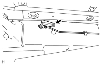
(c) Install the bracket with the bolt. Torque: 29 N·m {296 kgf·cm, 21 ft·lbf} |
|
.png)
(d) While using a wrench to hold the bracket, connect the joint.
Torque:
25 N·m {255 kgf·cm, 18 ft·lbf}
HINT:
For the joint that connects supplied parts, tighten the joint while checking the gap spacing shown in the illustration.
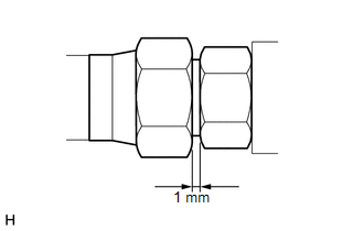
Standard clearance:
1 mm (0.0394 in.)
4. INSTALL CENTER CONTROL ABSORBER ASSEMBLY RH
HINT:
Use the same procedure described for the LH side.
5. INSTALL NO. 1 CENTER CONTROL ABSORBER TUBE LH
|
(a) Install a new No. 1 center control absorber tube with the bolt. Torque: 29 N·m {296 kgf·cm, 21 ft·lbf} |
|
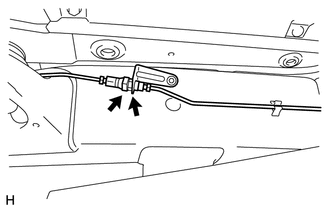
(b) While using a wrench to hold the center control absorber assembly, connect the joint.
.png)
Torque:
25 N·m {255 kgf·cm, 18 ft·lbf}
HINT:
For the joint that connects supplied tubes, tighten the joint while checking the gap spacing shown in the illustration.
Standard clearance:
1 mm (0.0394 in.)
(c) Pass the center control absorber tube between the body and frame.
|
(d) Attach the 2 clamps. |
|
.png)
(e) While using a wrench to hold the bracket, connect the joint.
Torque:
25 N·m {255 kgf·cm, 18 ft·lbf}
HINT:
For the joint that connects supplied tubes, tighten the joint while checking the gap spacing shown in the illustration.
Standard clearance:
1 mm (0.0394 in.)
(f) While using a wrench to hold the bracket, connect the joint.
.png)
Torque:
25 N·m {255 kgf·cm, 18 ft·lbf}
HINT:
For the joint that connects the supplied tubes, tighten the joint while checking the gap spacing shown in the illustration.
Standard clearance:
1 mm (0.0394 in.)
6. INSTALL NO. 1 CENTER CONTROL ABSORBER TUBE RH
HINT:
Use the same procedure described for the LH side.
7. INSTALL TUBE PROTECTOR LH
|
(a) Install the tube protector LH with the bolt. Torque: 29 N·m {296 kgf·cm, 21 ft·lbf} |
|
.png)
8. INSTALL TUBE PROTECTOR RH
HINT:
Use the same procedure described for the LH side.
9. INSTALL FRONT WHEEL
.gif)
10. INSTALL REAR WHEEL
11. INSPECT FOR FLUID LEAK
 Removal
REMOVAL
CAUTION / NOTICE / HINT
NOTICE:
Be sure to read PRECAUTION before performing this procedure (See page
).
PROCEDURE
1. REMOVE FRONT WHEEL
2. REMOVE REAR WHEEL
3. REMOVE CENTER CONTROL ...
 Disposal
DISPOSAL
PROCEDURE
1. DISPOSE OF CENTER CONTROL ABSORBER ASSEMBLY LH
(a) Using a drill, make a hole in the cylinder as shown in the illustration
to discharge the gas inside.
...
Other materials about Toyota 4Runner:
Tire Pressure Warning Light Circuit
DESCRIPTION
If the tire pressure warning ECU detects a disconnected connector or an open
circuit between the tire pressure warning ECU and combination meter, the tire pressure
warning light turns off 10 seconds after the ignition switch is turned to ON, b ...
System Diagram
SYSTEM DIAGRAM
Communication Table
Sender
Receiver
Signal
Line
Main Body ECU (Multiplex Network Body ECU)
Sliding Roof Drive Gear Sub-assembly (Sliding Roof ECU)
I ...

0.0073