Toyota 4Runner: Installation
INSTALLATION
PROCEDURE
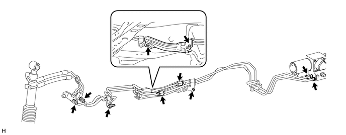
1. INSTALL STABILIZER CONTROL WITH ACCUMULATOR HOUSING ASSEMBLY
(a) Install the stabilizer control with accumulator housing with the 3 bolts.
Torque:
29 N·m {296 kgf·cm, 21 ft·lbf}
(b) Connect the connector, and then attach the clamp to the hole of the bracket.
2. INSTALL FRONT STABILIZER CONTROL TUBE
(a) Install a new front stabilizer control tube (front side and rear side).
(1) Apply suspension fluid to the threads of the flare nuts.
(2) Temporarily install the 6 flare nuts on the front stabilizer control tubes.
NOTICE:
- Do not bend the control tubes.
- Make sure that the control tubes do not contact other parts.
- Do not damage the control tubes or flare nuts.
(b) Install the 2 bolts.
Torque:
29 N·m {296 kgf·cm, 21 ft·lbf}
(c) Using a union nut wrench, tighten the 6 flare nuts on the front stabilizer control tubes.
Torque:
44 N·m {450 kgf·cm, 33 ft·lbf}
NOTICE:
Use the formula to calculate special torque values for situations where a union
nut wrench is combined with a torque wrench (See page
.gif) ).
).
3. INSTALL FRONT STABILIZER CONTROL TUBE INSULATOR
(a) Install the front stabilizer control tube insulator with the 2 bolts.
Torque:
10 N·m {102 kgf·cm, 7 ft·lbf}
4. INSTALL FRONT STABILIZER TUBE PROTECTOR
(a) Install the front stabilizer tube protector with the 2 bolts.
Torque:
29 N·m {296 kgf·cm, 21 ft·lbf}
5. INSTALL REAR STABILIZER CONTROL TUBE
(a) Install a new rear stabilizer control tube (front side and rear side).

(1) Apply suspension fluid to the threads of the flare nuts.
(2) Temporarily install the 4 flare nuts on the rear stabilizer control tubes.
NOTICE:
- Make sure that the control tubes do not contact other parts.
- Do not bend the control tubes.
- Do not damage the control tubes or flare nuts.
(b) Install the 5 bolts.
Torque:
29 N·m {296 kgf·cm, 21 ft·lbf}
(c) Using a union nut wrench, tighten the 4 flare nuts on the rear stabilizer control tubes.
Torque:
44 N·m {450 kgf·cm, 33 ft·lbf}
NOTICE:
Use the formula to calculate special torque values for situations where a union
nut wrench is combined with a torque wrench (See page
).
(d) Install the rear stabilizer control tubes to the rear stabilizer control cylinder with the 2 union bolts and 2 new pressure port gaskets.
Torque:
69 N·m {704 kgf·cm, 51 ft·lbf}
NOTICE:
Insert the stoppers of the rear stabilizer control tubes into the rear stabilizer control cylinder.
6. BLEED AIR FROM SUSPENSION FLUID
7. APPLY PRESSURE ACCORDING TO TEMPERATURE MANAGEMENT CHART WHEN FILLING FLUID
8. INSPECT FOR SUSPENSION FLUID LEAK
9. INSTALL FRONT WHEEL
10. INSTALL REAR WHEEL
11. INSPECT VEHICLE HEIGHT
12. INSTALL NO. 1 ENGINE UNDER COVER SUB-ASSEMBLY
13. INSTALL STABILIZER CONTROL VALVE PROTECTOR
(a) Install the stabilizer control valve protector with the 2 bolts.
Torque:
29 N·m {296 kgf·cm, 21 ft·lbf}
14. INSTALL SIDE STEP ASSEMBLY LH
15. CONNECT CABLE TO NEGATIVE BATTERY TERMINAL
NOTICE:
When disconnecting the cable, some systems need to be initialized after the cable
is reconnected (See page ).
 Components
COMPONENTS
ILLUSTRATION
ILLUSTRATION
ILLUSTRATION
ILLUSTRATION
ILLUSTRATION
...
 Removal
REMOVAL
PROCEDURE
1. DISCONNECT CABLE FROM NEGATIVE BATTERY TERMINAL
CAUTION:
Wait at least 90 seconds after disconnecting the cable from the negative (-)
battery terminal to disable the SRS sys ...
Other materials about Toyota 4Runner:
Front Clearance Sonar Sensor LH Circuit
DESCRIPTION
The ultrasonic sensor sends and receives ultrasonic waves. Based on the received
wave, the sensor calculates the approximate distance between the vehicle and the
obstacle, and sends the distance value as a signal to the clearance warning ECU
...
ID Code Box Power Source Circuit
DESCRIPTION
This circuit provides power to operate the ID code box.
WIRING DIAGRAM
CAUTION / NOTICE / HINT
NOTICE:
Inspect the fuses for circuits related to this system before performing the following
inspection procedure.
PROCEDURE
1.
...

0.0273