Toyota 4Runner: Installation
INSTALLATION
CAUTION / NOTICE / HINT
HINT:
- Use the same procedure for the RH and LH sides.
- The procedure listed below is for the LH side.
PROCEDURE
1. INSTALL FRONT DOOR INSIDE LOCKING CABLE ASSEMBLY LH
.gif)
2. INSTALL FRONT DOOR LOCK REMOTE CONTROL CABLE ASSEMBLY LH
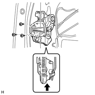
3. INSTALL FRONT DOOR LOCK ASSEMBLY LH
NOTICE:
- When reusing the removed front door lock assembly, replace the door lock wiring harness seal on the connector with a new one.
- Do not allow grease or dust to adhere to the surface of the connector which contacts the door lock wiring harness seal.
- Reusing the door lock wiring harness seal or using a damaged door lock wiring harness seal may allow water to enter into the connection. This may result in a malfunction of the front door lock assembly.
(a) Apply MP grease to the sliding parts of the front door lock assembly.
(b) Install a new door lock wiring harness seal to the front door lock assembly.
(c) Insert the front door lock open rod into the front door lock assembly.
(d) Check that the front door lock open rod is securely connected to the front door lock assembly.
(e) Using a T30 "TORX" wrench, install the front door lock assembly with the 3 screws.
Torque:
5.0 N·m {51 kgf·cm, 44 in·lbf}
(f) Connect the connector.
4. INSTALL FRONT DOOR OUTSIDE HANDLE COVER LH
5. INSTALL FRONT DOOR REAR LOWER FRAME SUB-ASSEMBLY LH
6. INSTALL FRONT DOOR GLASS RUN LH
7. INSTALL FRONT DOOR GLASS SUB-ASSEMBLY LH
8. INSTALL FRONT DOOR SERVICE HOLE COVER LH
9. INSTALL FRONT DOOR INNER GLASS WEATHERSTRIP LH
10. INSTALL FRONT DOOR TRIM BOARD SUB-ASSEMBLY LH
11. INSTALL DOOR NO. 2 INSIDE HANDLE BEZEL LH
12. INSTALL FRONT DOOR LOWER FRAME BRACKET GARNISH LH
13. CONNECT CABLE TO NEGATIVE BATTERY TERMINAL
NOTICE:
When disconnecting the cable, some systems need to be initialized after the cable
is reconnected (See page ).
14. CHECK SRS WARNING LIGHT
(a) Check the SRS warning light (See page ).
 Inspection
INSPECTION
PROCEDURE
1. INSPECT FRONT DOOR LOCK ASSEMBLY LH
(a) Check the door lock motor operation.
(1) Apply battery voltage to the motor connector and check the operation of the
door lock.
...

Other materials about Toyota 4Runner:
Customize Parameters
CUSTOMIZE PARAMETERS
1. CUSTOMIZING FUNCTION WITH TECHSTREAM
HINT:
The following items can be customized.
NOTICE:
When the customer requests a change in a function, first make sure that
the function can be customized.
Be sure to make a not ...
If the electronic key does not operate properly (vehicles with a smart key
system)
If communication between the electronic key and vehicle is interrupted
or the electronic key cannot be used because the battery is depleted, the smart
key system and wireless remote control cannot be used. In such cases, the doors
can be opened and ...

0.026