Toyota 4Runner: Installation
INSTALLATION
PROCEDURE
1. INSTALL STEREO COMPONENT AMPLIFIER ASSEMBLY
(a) Install the stereo component amplifier to the No. 1 speaker assembly with box with the 3 bolts.
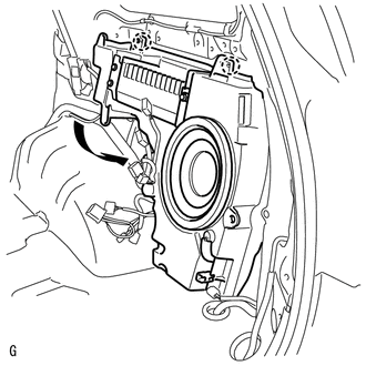
2. INSTALL NO. 1 SPEAKER ASSEMBLY WITH BOX
|
(a) Attach the 2 claws, lower the No. 1 speaker assembly with box in the direction of the arrow and set it in place. |
|
(b) Install the No. 1 speaker assembly with box with the 4 bolts.
Torque:
2.5 N·m {25 kgf·cm, 22 in·lbf}
(c) Connect the 5 connectors.
3. INSTALL DECK TRIM SIDE PANEL ASSEMBLY RH
.gif)
4. INSTALL NO. 1 LUGGAGE COMPARTMENT TRIM COVER
5. INSTALL FRONT DECK SIDE TRIM COVER RH
6. INSTALL FRONT DECK SIDE TRIM COVER LH
7. INSTALL NO. 1 LUGGAGE COMPARTMENT TRIM HOOK
8. INSTALL REAR NO. 1 SEAT OUTER LAP BELT ANCHOR COVER
9. INSTALL REAR FLOOR CARPET ASSEMBLY (w/o Deck Board)
10. INSTALL REAR FLOOR MAT REAR SUPPORT PLATE
11. INSTALL INNER FLOOR SIDE RAIL SUB-ASSEMBLY (w/ Deck Board)
12. INSTALL DECK BOARD ASSEMBLY (w/ Deck Board)
13. INSTALL LUGGAGE COMPARTMENT SIDE COVER SUB-ASSEMBLY RH (w/ Deck Board)
14. INSTALL LUGGAGE COMPARTMENT SIDE COVER SUB-ASSEMBLY LH (w/ Deck Board)
15. INSTALL NO. 2 REAR FLOOR BOARD ASSEMBLY (w/ Deck Board)
16. INSTALL NO. 2 DECK BOARD SUB-ASSEMBLY (w/ Deck Board)
17. INSTALL NO. 2 LUGGAGE COMPARTMENT TRIM COVER (w/ Deck Board, w/o Rear No. 2 Seat)
18. INSTALL NO. 1 DECK BOARD SUB-ASSEMBLY (w/o Deck Board)
19. INSTALL NO. 1 LUGGAGE COMPARTMENT TRIM COVER (w/o Deck Board)
20. INSTALL OUTER LAP BELT ANCHOR COVER
21. INSTALL REAR DOOR OPENING TRIM WEATHERSTRIP RH
22. INSTALL REAR DOOR SCUFF PLATE RH
23. INSTALL QUARTER SCUFF PLATE RH (w/ Rear No. 2 Seat)
24. INSTALL REAR NO. 1 FLOOR STEP COVER (w/ Rear No. 2 Seat)
 Inspection
INSPECTION
PROCEDURE
1. INSPECT NO. 1 SPEAKER ASSEMBLY WITH BOX
(a) Measure the resistance according to the value(s) in the table below.
Standard Resistance:
Test ...
 Microphone Amplifier
Components
COMPONENTS
ILLUSTRATION
ILLUSTRATION
Removal
REMOVAL
PROCEDURE
1. REMOVE DRIVE MONITOR SWITCH
2. REMOVE MAP LIGHT ASSEMBLY
3. REMOVE TELEPHONE MICROPHONE ASSEMBLY
...
Other materials about Toyota 4Runner:
Runnable Signal Malfunction (B2286,P0335)
DESCRIPTION
The power management control ECU and ECM are connected by a cable and the CAN
communication lines. These DTCs are stored when the crankshaft position sensor signal
information from the cable and the crankshaft position sensor signal informatio ...
Tire inflation pressure
Tire inflation pressure
The recommended cold tire inflation pressure and tire size are displayed on
the tire and loading information label.
Inspection and adjustment procedure
1. Tire valve 2. Tire pressure gauge
Remove the tire valve cap.
Press t ...

0.0251