Toyota 4Runner: Installation
INSTALLATION
PROCEDURE
1. INSTALL NO. 1 ULTRASONIC SENSOR RETAINER
|
(a) Align the keyhole and protrusion as shown in the illustration. Text in Illustration
|
|
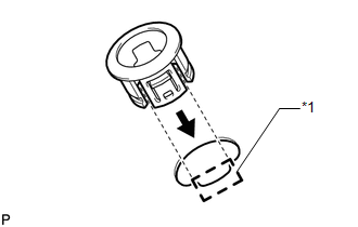
(b) Attach the 4 claws to install the No. 1 ultrasonic sensor retainer to the rear bumper cover.
NOTICE:
Do not damage the bumper cover with the protrusion when installing the No. 1 ultrasonic sensor retainer.
HINT:
Use the same procedure as for the other side.
2. INSTALL NO. 2 ULTRASONIC SENSOR RETAINER
|
(a) Align the keyhole and protrusion as shown in the illustration. Text in Illustration
|
|
.png)
(b) Attach the 3 claws to install the No. 2 ultrasonic sensor retainer to the rear bumper cover.
NOTICE:
Do not damage the bumper cover with the protrusion when installing the No. 2 ultrasonic sensor retainer.
HINT:
Use the same procedure as for the other side.
3. INSTALL ULTRASONIC SENSOR CLIP
(a) Attach the claw to install the ultrasonic sensor clip to the No. 1 ultrasonic sensor.
HINT:
Use the same procedure as for the other side.
4. INSTALL NO. 1 ULTRASONIC SENSOR
(a) Attach the 2 claws to install the No. 1 ultrasonic sensor to the ultrasonic sensor retainer.
HINT:
Use the same procedure as for the other side.
5. INSTALL NO. 3 FLOOR WIRE
.gif)
6. INSTALL REAR BUMPER COVER
7. INSTALL REAR QUARTER PANEL MUDGUARD LH
8. INSTALL REAR QUARTER PANEL MUDGUARD RH
HINT:
Use the same procedure as for the LH side.
9. INSTALL JACK BOX HOLE COVER
 Inspection
INSPECTION
PROCEDURE
1. INSPECT NO. 1 ULTRASONIC SENSOR
(a) Measure the resistance according to the value(s) in the table below.
Standard Resistance:
Tester Connection
Co ...
 Brake (front)
...
Other materials about Toyota 4Runner:
IG Signal Circuit
DESCRIPTION
This circuit detects the ignition switch ON or off condition, and sends it to
the main body ECU.
WIRING DIAGRAM
CAUTION / NOTICE / HINT
NOTICE:
Inspect the fuses for circuits related to this system before performing the following
inspect ...
Crawl Switch
Components
COMPONENTS
ILLUSTRATION
Removal
REMOVAL
PROCEDURE
1. REMOVE DRIVE MONITOR SWITCH (CRAWL CONTROL SWITCH AND MULTI-TERRAIN SELECT
SWITCH)
(a) Detach the 4 claws and remove the drive monitor switch (CRAWL control
switch an ...

0.0257