Toyota 4Runner: Installation
INSTALLATION
PROCEDURE
1. INSTALL BRAKE PEDAL SUPPORT ASSEMBLY
(a) Temporarily install the set bolt.
(b) Install the hydraulic brake booster (See page
.gif) ).
).
(c) tighten the brake pedal support sub-assembly with the 4 nuts.
Torque:
14 N·m {145 kgf·cm, 10 ft·lbf}
(d) Tighten the brake pedal support reinforcement set bolt.
Torque:
20 N·m {204 kgf·cm, 15 ft·lbf}
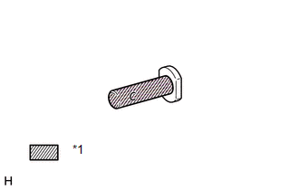
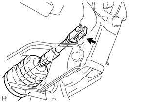
2. INSTALL PUSH ROD PIN
|
(a) Apply a light coat of lithium soap base glycol grease to the inner surface of the hole in the brake pedal lever. Text in Illustration
|
|
|
(b) Set the master cylinder push rod clevis in place, insert the push rod pin from the left side of the vehicle, and then install a new clip. |
|
3. INSTALL BRAKE PEDAL RETURN SPRING
(a) Apply a light coat of lithium soap base glycol grease to inner surface of the hole in the brake pedal support sub-assembly.
(b) Install the brake pedal return spring to the brake pedal support sub-assembly.
4. INSTALL STOP LIGHT SWITCH ASSEMBLY
(a) Install the stop light switch (See page
).
(b) Connect the stop light switch connector.
5. INSTALL LOWER NO. 1 INSTRUMENT PANEL AIRBAG ASSEMBLY
(a) Install the lower No. 1 instrument panel airbag assembly (See page
).
6. CONNECT CABLE FROM NEGATIVE BATTERY TERMINAL
NOTICE:
When disconnecting the cable, some systems need to be initialized after the cable
is reconnected (See page ).
7. BLEED BRAKE SYSTEM
8. CHECK AND ADJUST BRAKE PEDAL
(a) Check and adjust brake pedal (See page ).
 Reassembly
REASSEMBLY
PROCEDURE
1. INSTALL STOP LIGHT SWITCH MOUNTING ADJUSTER
(a) Install a new stop light switch mounting adjuster to the brake pedal support.
2. INSTALL BRAKE PEDAL PAD
(a) Install the br ...

Other materials about Toyota 4Runner:
Evaporator Temperature Sensor Circuit (B1413)
DESCRIPTION
The No. 1 cooler thermistor is installed on the evaporator in the air conditioning
unit to detect the temperature of the cooled air that has passed through the evaporator
and control the air conditioning. It sends appropriate signals to the No ...
Open in Motor LH Circuit (22,24)
DESCRIPTION
When there is an open in the side auto step motor circuit, the side auto step
controller ECU assembly does not operate the automatic running board.
DTC No.
Detection Condition
Trouble Area
22
...

0.0268