Toyota 4Runner: Installation
INSTALLATION
PROCEDURE
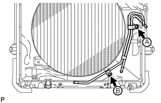
1. INSTALL NO. 2 OIL COOLER TUBE SUB-ASSEMBLY
|
(a) Temporarily install the oil cooler tube to the fan shroud with bolt A. Install bolt B and tighten it to the specified torque. Then tighten bolt A to the specified torque. Torque: 5.5 N·m {56 kgf·cm, 49 in·lbf} |
|
2. INSTALL NO. 2 OIL COOLER INLET HOSE AND NO. 2 OIL COOLER OUTLET HOSE
|
(a) Connect the No. 2 oil cooler inlet hose and No. 2 oil cooler outlet hose to the No. 2 oil cooler tube. Text in Illustration
|
|
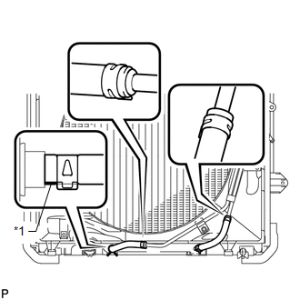
(b) Connect the 2 hoses to the radiator to install them.
NOTICE:
- When connecting the hoses to the tube, support the tube by hand and be careful to prevent the tube from being deformed.
- Make sure the paint mark and pinching portion of each clip are facing the directions shown in the illustration.
3. INSTALL NO. 1 INLET OIL COOLER TUBE AND NO. 1 OUTLET OIL COOLER TUBE
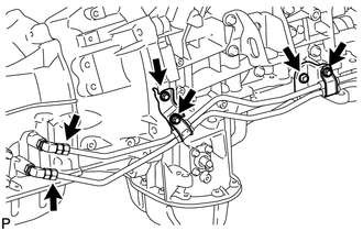
(a) Install the 2 No. 2 flexible hose clamps with the 2 bolts.
Torque:
14 N·m {143 kgf·cm, 10 ft·lbf}
(b) Temporarily install the ends of the 2 oil cooler tubes to each oil cooler tube union by hand.
(c) Close the 2 No. 2 flexible hose clamps and install the 2 bolts.
Torque:
5.5 N·m {56 kgf·cm, 49 in·lbf}
(d) Using a union nut wrench, tighten the inlet and outlet tubes.
Torque:
34 N·m {347 kgf·cm, 25 ft·lbf}
NOTICE:
Use the formula to calculate special torque values for situations where a union
nut wrench is combined with a torque wrench (See page
.gif) ).
).
4. INSTALL NO. 1 OIL COOLER INLET HOSE AND NO. 1 OIL COOLER OUTLET HOSE
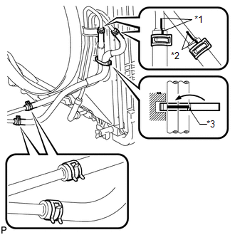
(a) Connect the No. 1 oil cooler inlet hose and No. 1 oil cooler outlet hose to the oil cooler inlet tube and No. 1 oil cooler outlet tube.
Text in Illustration|
*1 |
Blue Paint Mark |
|
*2 |
Pink Paint Mark |
|
*3 |
White Paint Mark |
(b) Connect the 2 hoses to the No. 2 oil cooler tube to install them, and then pass the 2 hoses through the No. 1 flexible hose clamp and close the clamp.
NOTICE:
- When connecting the hoses to the tube, support the tube by hand and be careful to prevent the tube from being deformed.
- Make sure the paint marks and pinching portion of each clip are facing the directions shown in the illustration.
5. ADJUST AUTOMATIC TRANSMISSION FLUID LEVEL
(a) Adjust the automatic transmission fluid level (See page
).
6. INSTALL FRONT NO. 1 FENDER APRON TO FRAME SEAL RH
7. INSTALL FRONT FENDER APRON SEAL RH
8. INSTALL REAR ENGINE UNDER COVER ASSEMBLY
9. INSTALL NO. 1 ENGINE UNDER COVER SUB-ASSEMBLY
 Components
COMPONENTS
ILLUSTRATION
ILLUSTRATION
...
 Removal
REMOVAL
PROCEDURE
1. REMOVE NO. 1 ENGINE UNDER COVER SUB-ASSEMBLY
2. REMOVE REAR ENGINE UNDER COVER ASSEMBLY
3. REMOVE FRONT FENDER APRON SEAL RH
4. REMOVE FRONT NO. 1 FENDER APRON TO FR ...
Other materials about Toyota 4Runner:
Reassembly
REASSEMBLY
CAUTION / NOTICE / HINT
CAUTION:
Wear protective gloves. Sharp areas on the parts may injure your hands.
PROCEDURE
1. INSTALL FRONT SEAT SIDE AIRBAG ASSEMBLY
2. INSTALL SEPARATE TYPE FRONT SEATBACK COVER
(a) Using hog ring plier ...
High Mounted Stop Light Assembly
Components
COMPONENTS
ILLUSTRATION
Removal
REMOVAL
PROCEDURE
1. REMOVE CENTER STOP LIGHT ASSEMBLY
(a) Remove the 2 screws and stop light.
(b) Disconnect the connector.
Inspection
INSPECTION ...

0.0066