Toyota 4Runner: Installation
INSTALLATION
CAUTION / NOTICE / HINT
HINT:
- Use the same procedure for the RH and LH sides.
- The procedure listed below is for the LH side.
PROCEDURE
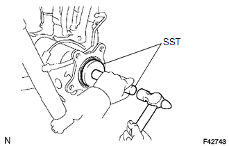
1. INSTALL REAR AXLE SHAFT OIL SEAL LH
|
(a) Using SST and a hammer, install a new axle shaft oil seal. SST: 09950-60020 09951-00770 SST: 09950-70010 09951-07150 NOTICE: Do not allow foreign matter, etc. to contact the axle shaft housing hole. |
|
2. INSTALL REAR AXLE SHAFT WITH PARKING BRAKE PLATE LH
(a) Install a new O-ring to the axle housing.
(b) Install the rear axle shaft with parking brake plate with the 4 nuts.
Torque:
60 N·m {612 kgf·cm, 44 ft·lbf}
3. INSTALL PARKING BRAKE ASSEMBLY
(a) Install the parking brake assembly (See page
.gif) ).
).
4. INSTALL REAR SPEED SENSOR LH
5. CONNECT REAR FLEXIBLE HOSE LH
6. FILL RESERVOIR WITH BRAKE FLUID
7. BLEED BRAKE LINE
8. CHECK BRAKE FLUID LEVEL IN RESERVOIR
9. INSPECT FOR BRAKE FLUID LEAK
10. CONNECT CABLE TO NEGATIVE BATTERY TERMINAL
NOTICE:
When disconnecting the cable, some systems need to be initialized after the cable
is reconnected (See page ).
11. INSTALL REAR WHEEL
Torque:
for aluminum wheel :
103 N·m {1050 kgf·cm, 76 ft·lbf}
for steel wheel :
112 N·m {1142 kgf·cm, 83 ft·lbf}
12. INSPECT PARKING BRAKE PEDAL TRAVEL
13. CHECK SPEED SENSOR SIGNAL
(a) Check the speed sensor signal (See page
).
 Reassembly
REASSEMBLY
CAUTION / NOTICE / HINT
NOTICE:
Do not allow foreign matter, etc. to contact the rear axle hub and bearing assembly.
PROCEDURE
1. INSTALL BRAKE DRUM OIL DEFLECTOR LH
(a) Install a n ...

Other materials about Toyota 4Runner:
Disassembly
DISASSEMBLY
CAUTION / NOTICE / HINT
PROCEDURE
1. REMOVE OUTER MIRROR LH
(a) Put protective tape around the outer mirror LH.
(b) Using a moulding remover, detach the 2 claws of the outer mirror
LH as shown in the illustration.
Text in Ill ...
Parts Location
PARTS LOCATION
ILLUSTRATION
ILLUSTRATION
ILLUSTRATION
ILLUSTRATION
ILLUSTRATION
...

0.0079