Toyota 4Runner: Installation
INSTALLATION
PROCEDURE
1. INSTALL FRONT DRIVE SHAFT ASSEMBLY
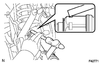
(a) Coat the spline of the inboard joint shaft assembly with ATF.
(b) Align the shaft splines and install the drive shaft with a brass bar and hammer.
NOTICE:
- Set the snap ring with the opening facing downward.
- Be careful not to damage the oil seal, boot or dust cover.
HINT:
Whether the inboard joint shaft is in contact with the pinion shaft or not can be confirmed from the sound or feeling when tapping in the shaft.
2. INSTALL FRONT SPEED SENSOR
.gif)
3. INSTALL LOWER BALL JOINT ATTACHMENT LH
(a) Install the lower ball joint attachment with the 2 bolts.
Torque:
160 N·m {1631 kgf·cm, 118 ft·lbf}
4. CONNECT TIE ROD END SUB-ASSEMBLY LH
5. INSTALL FRONT AXLE SHAFT NUT
6. INSTALL FRONT GREASE HUB CAP
7. ADD DIFFERENTIAL OIL
8. INSPECT DIFFERENTIAL OIL
9. INSTALL FRONT WHEEL
Torque:
for aluminum wheel :
103 N·m {1050 kgf·cm, 76 ft·lbf}
for steel wheel :
112 N·m {1142 kgf·cm, 83 ft·lbf}
10. CHECK FRONT SPEED SENSOR SIGNAL
(a) Check the front speed sensor signal (See page
).
 Inspection
INSPECTION
PROCEDURE
1. INSPECT FRONT DRIVE SHAFT ASSEMBLY
NOTICE:
Keep the drive shaft level while handling it.
(a) Check if there is excessive play in the outboard joint.
(b) Check if the in ...
 Reassembly
REASSEMBLY
PROCEDURE
1. INSTALL FRONT DRIVE SHAFT DUST COVER
(a) Using SST and a press, install a new dust cover.
SST: 09527-10011
2. INSTALL SHAFT SNAP RING
(a) Install a new snap ring.
3. ...
Other materials about Toyota 4Runner:
Washer Nozzle(for Rear Side)
Components
COMPONENTS
ILLUSTRATION
On-vehicle Inspection
ON-VEHICLE INSPECTION
CAUTION / NOTICE / HINT
HINT:
The washer fluid does not spray if the back door and back door glass are not
closed.
PROCEDURE
1. INSPECT REAR WASHER NOZZLE
(a) With ...
Outside Vehicle
General Maintenance
GENERAL MAINTENANCE
CAUTION / NOTICE / HINT
Performing the following maintenance checks on the vehicle is the owner's
responsibility. The owner may perform the maintenance or take the vehicle
to a service center. Che ...

0.0257