Toyota 4Runner: Inverter Main Switch
Components
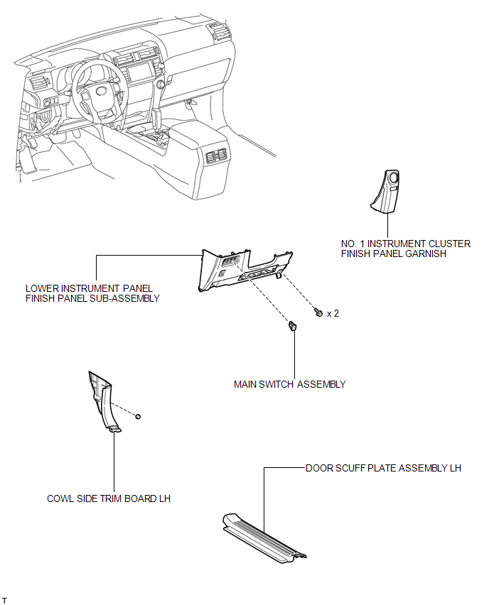
COMPONENTS
ILLUSTRATION
Installation
INSTALLATION
PROCEDURE
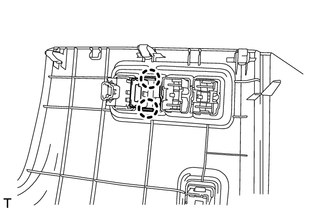
1. INSTALL MAIN SWITCH ASSEMBLY
(a) Attach the 2 claws to install the main switch.
2. INSTALL LOWER INSTRUMENT PANEL FINISH PANEL SUB-ASSEMBLY
.gif)
3. INSTALL COWL SIDE TRIM BOARD LH
4. INSTALL DOOR SCUFF PLATE ASSEMBLY LH
5. INSTALL NO. 1 INSTRUMENT CLUSTER FINISH PANEL GARNISH
Removal
REMOVAL
PROCEDURE
1. REMOVE NO. 1 INSTRUMENT CLUSTER FINISH PANEL GARNISH
.gif)
2. REMOVE DOOR SCUFF PLATE ASSEMBLY LH
3. REMOVE COWL SIDE TRIM BOARD LH
4. REMOVE LOWER INSTRUMENT PANEL FINISH PANEL SUB-ASSEMBLY
5. REMOVE MAIN SWITCH ASSEMBLY
|
(a) Detach the 2 claws and remove the main switch. |
|
 Removal
REMOVAL
PROCEDURE
1. REMOVE NO. 1 INSTRUMENT CLUSTER FINISH PANEL GARNISH
2. REMOVE NO. 2 INSTRUMENT CLUSTER FINISH PANEL GARNISH
3. REMOVE FRONT NO. 1 CONSOLE BOX INSERT
4. REMOVE FRONT ...

Other materials about Toyota 4Runner:
Installation
INSTALLATION
CAUTION / NOTICE / HINT
HINT:
A bolt without a torque specification is shown in the standard bolt chart (See
page ).
PROCEDURE
1. INSTALL POWER MANAGEMENT CONTROL ECU
(a) Attach the 2 claws to install the power management control ECU.
2. ...
Inspection
INSPECTION
PROCEDURE
1. INSPECT DOOR CONTROL SWITCH ASSEMBLY
(a) Measure the resistance according to the value(s) in the table below.
Standard Resistance:
Tester Connection
Condition
Speci ...

0.0268