Toyota 4Runner: Lost Communication with Front Satellite Sensor Bus (B161A/8A)
DESCRIPTION
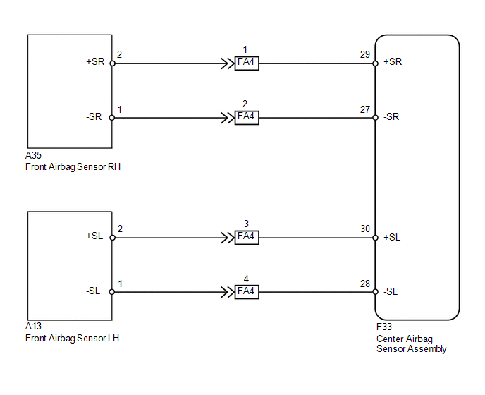
The front collision sensor circuit (front airbag sensor RH circuit and front airbag sensor LH circuit) is composed of the center airbag sensor assembly, front airbag sensor RH and front airbag sensor LH.
The front airbag sensor RH or front airbag sensor LH detects impacts to the vehicle and sends signals to the center airbag sensor assembly to determine if the airbag should be deployed.
DTC B161A/8A is stored when a malfunction is detected in the front collision sensor circuit (front airbag sensor RH circuit and front airbag sensor LH circuit).
|
DTC Code |
DTC Detection Condition |
Trouble Area |
|---|---|---|
|
B161A/8A |
One of the following conditions is met:
|
|
WIRING DIAGRAM
CAUTION / NOTICE / HINT
NOTICE:
When disconnecting the cable from the negative (-) battery terminal while performing
repairs, some systems need to be initialized after the cable is reconnected (See
page .gif) ).
).
PROCEDURE
|
1. |
CHECK FOR DTC |
(a) Turn the ignition switch to ON, and wait for at least 60 seconds.
(b) Turn the ignition switch off.
HINT:
If a communication error occurs, DTCs for both the LH and RH sides will be stored simultaneously. To identify the malfunctioning area, turn the ignition switch off and then to ON again.
(c) Turn the ignition switch to ON, and wait for at least 60 seconds.
(d) Check for DTCs (See page ).
Result
|
Result |
Proceed to |
|---|---|
|
DTCs B1613 and B1618 are not output |
A |
|
DTC B1613 is output |
B |
|
DTC B1618 is output |
C |
HINT:
- DTCs indicating communication errors will be changed to DTCs indicating errors in initialization by turning the ignition switch off and then to ON again.
- Codes other than DTCs B1613 and B1618 may be output at this time, but they are not related to this check.
| B | .gif) |
GO TO DTC B1613/83 |
| C | |
GO TO DTC B1618/84 |
|
.gif)
|
2. |
CHECK CENTER AIRBAG SENSOR ASSEMBLY |
(a) Turn the ignition switch to ON, and wait for at least 60 seconds.
(b) Clear the DTCs stored in memory (See page
).
(c) Turn the ignition switch off.
(d) Turn the ignition switch to ON, and wait for at least 60 seconds.
(e) Check for DTCs (See page ).
OK:
DTC B161A is not output.
HINT:
Codes other than DTC B161A may be output at this time, but they are not related to this check.
| OK | |
USE SIMULATION METHOD TO CHECK |
| NG | |
REPLACE CENTER AIRBAG SENSOR ASSEMBLY |
 Rear Airbag Sensor Assembly RH Initialization Incomplete (B1633/81,B1638/82)
DESCRIPTION
The circuit for the side collision sensor LH or RH (to determine deployment of
the front seat side airbag LH or RH and curtain shield airbag LH or RH) is composed
of the center airbag ...
 Lost Communication with Front Airbag Sensor LH (B1617/84,B1618/84)
DESCRIPTION
The front airbag sensor LH circuit consists of the center airbag sensor and front
airbag sensor LH.
The front airbag sensor LH detects impacts to the vehicle and sends signals to
the ...
Other materials about Toyota 4Runner:
Acceleration Sensor Power Supply Voltage Malfunction (C1381)
DESCRIPTION
The skid control ECU receives signals from the yaw rate and acceleration sensor
via the CAN communication system.
The yaw rate sensor has a built-in acceleration sensor and detects the vehicle's
condition using 2 circuits (GL1, GL2).
If ...
Checking and replacing fuses
If any of the electrical components do not operate, a fuse may have blown.
If this happens, check and replace the fuses as necessary.
Vehicles without a smart key
system Turn the engine switch off. Vehicles with a smart key
system
Turn the “ENGINE ...

0.0295