Toyota 4Runner: Lost Communication with "Seat Control Module A" (U0208)
DESCRIPTION
|
DTC Code |
DTC Detection Condition |
Trouble Area |
|---|---|---|
|
U0208 |
There is no communication from the front power seat switch LH. |
|
HINT:
For vehicles with a seat position memory only.
WIRING DIAGRAM

CAUTION / NOTICE / HINT
NOTICE:
Inspect the fuses for circuits related to this system before performing the following inspection procedure.
HINT:
Operating the ignition switch, any switches or any doors triggers related ECU and sensor communication with the CAN, which causes resistance variation.
PROCEDURE
|
1. |
DISCONNECT CABLE FROM NEGATIVE BATTERY TERMINAL |
(a) Disconnect the cable from the negative (-) battery terminal before measuring the resistances of the main wire and branch wire.
CAUTION:
Wait at least 90 seconds after disconnecting the cable from the negative (-) battery terminal to disable the SRS system.
NOTICE:
- When disconnecting the cable, some systems need to be initialized after
the cable is reconnected (See page
.gif) ).
).
|
.gif)
|
2. |
CHECK FOR OPEN IN CAN BUS WIRE (FRONT POWER SEAT SWITCH LH BRANCH WIRE) |
|
(a) Disconnect the b19 front power seat switch LH connector. |
|
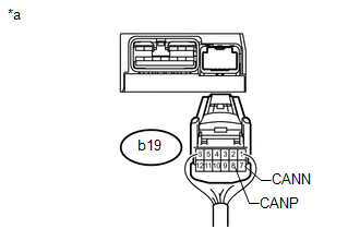
(b) Measure the resistance according to the value(s) in the table below.
Standard Resistance:
|
Tester Connection |
Switch Condition |
Specified Condition |
|---|---|---|
|
b19-8 (CANP) - b19-7 (CANN) |
Ignition switch off |
54 to 69 Ω |
|
*a |
Rear view of wire harness connector (to Front Power Seat Switch LH) |
| NG | .gif) |
REPAIR OR REPLACE FRONT POWER SEAT SWITCH LH CAN BRANCH WIRE OR CONNECTOR (CANP, CANN) |
|
|
3. |
CHECK HARNESS AND CONNECTOR (FRONT POWER SEAT SWITCH LH - BATTERY AND BODY GROUND) |
|
(a) Connect the cable to the negative (-) battery terminal. NOTICE: When disconnecting the cable, some systems need to be initialized after
the cable is reconnected (See page |
|
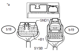
(b) Disconnect the b18 front power seat switch LH connector.
(c) Measure the resistance according to the value(s) in the table below.
Standard Resistance:
|
Tester Connection |
Condition |
Specified Condition |
|---|---|---|
|
b18-2 (GND1) - Body ground |
Always |
Below 1 Ω |
(d) Measure the voltage according to the value(s) in the table below.
Standard Voltage:
|
Tester Connection |
Condition |
Specified Condition |
|---|---|---|
|
b18-7 (+B1) - Body ground |
Always |
11 to 14 V |
|
b19-12 (SYSB) - Body ground |
Always |
11 to 14 V |
|
*a |
Rear view of wire harness connector (to Front Power Seat Switch LH) |
| OK | |
REPLACE FRONT POWER SEAT SWITCH LH |
| NG | |
REPAIR OR REPLACE HARNESS OR CONNECTOR |
 Lost Communication with ECM / PCM "A" (U0100)
DESCRIPTION
DTC Code
DTC Detection Condition
Trouble Area
U0100
There is no communication from the ECM.
Power source ...
 Lost Communication with A/C ECU (U0164)
DESCRIPTION
DTC Code
DTC Detection Condition
Trouble Area
U0164
There is no communication from the air conditioning amplifier assembly.
...
Other materials about Toyota 4Runner:
Data List / Active Test
DATA LIST / ACTIVE TEST
1. READ DATA LIST
HINT:
Using the Techstream to read the Data List allows the values or states of switches,
sensors, actuators and other items to be read without removing any parts. This non-intrusive
inspection can be very usefu ...
Installation
INSTALLATION
PROCEDURE
1. INSTALL REAR STABILIZER LINK ASSEMBLY
(a) Install the rear stabilizer link assembly with the bolt and nut.
Torque:
100 N·m {1020 kgf·cm, 74 ft·lbf}
HINT:
Turn the nut while holding the bolt.
2. INSTALL REAR STABILIZER CONT ...

0.027