Toyota 4Runner: Manual(sos)switch
Components
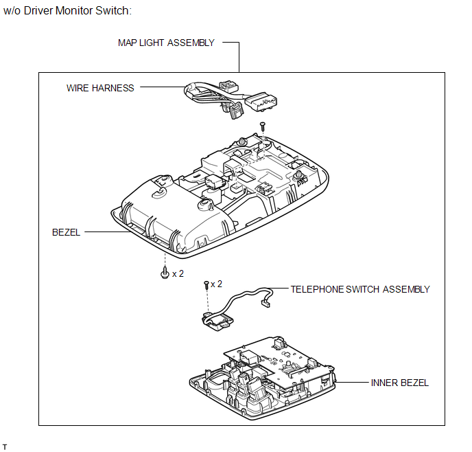
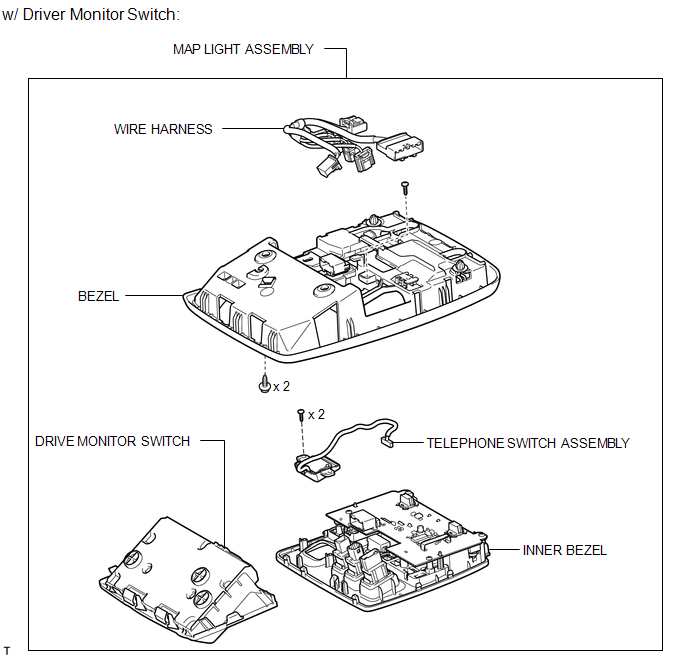
COMPONENTS
ILLUSTRATION
ILLUSTRATION
Installation
INSTALLATION
PROCEDURE
1. INSTALL TELEPHONE SWITCH ASSEMBLY
(a) Install the telephone switch with the 2 screws.
(b) Connect the connector.
(c) Attach the 8 claws to install the inner bezel.
(d) Install the screw.
(e) Connect the 6 connectors.
2. INSTALL MAP LIGHT ASSEMBLY
.gif)
3. INSTALL DRIVE MONITOR SWITCH
Removal
REMOVAL
PROCEDURE
1. REMOVE DRIVE MONITOR SWITCH
.gif)
2. REMOVE MAP LIGHT ASSEMBLY
3. REMOVE TELEPHONE SWITCH ASSEMBLY
|
(a) Disconnect the 6 connectors. |
|
.png)
|
(b) Remove the screw. |
|
.png)
|
(c) Detach the 8 claws and remove the inner bezel. |
|
.png)
|
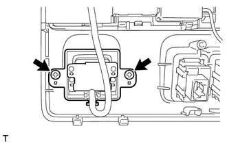
(d) Remove the 2 screws and telephone switch. |
|
 Installation
INSTALLATION
PROCEDURE
1. INSTALL NO. 2 TELEPHONE BRACKET
(a) Install the bracket with the 2 bolts.
2. INSTALL NO. 1 TELEPHONE BRACKET
(a) Install the bracket with the 3 bolts.
(b) Connect the 2 ...
 Mayday Battery
Components
COMPONENTS
ILLUSTRATION
Removal
REMOVAL
PROCEDURE
1. DISCONNECT CABLE FROM NEGATIVE BATTERY TERMINAL
NOTICE:
When disconnecting the cable, some systems need to be initialized ...
Other materials about Toyota 4Runner:
Steering Angle Sensor Circuit (C15F1)
DESCRIPTION
The power steering ECU assembly receives steering angle signals from the steering
angle sensor via CAN communication. The power steering ECU assembly provides appropriate
assisting force in accordance with the steering angle signal.
...
Terminals Of Ecu
TERMINALS OF ECU
1. CHECK DRIVER SIDE JUNCTION BLOCK ASSEMBLY AND MAIN BODY ECU (MULTIPLEX NETWORK
BODY ECU)
(a) Remove the main body ECU (multiplex network body ECU) (See page
).
(b) Measure the voltage and resistance according to the value(s) in the ...

0.0153