Toyota 4Runner: Microphone Circuit between Microphone and Radio Receiver
DESCRIPTION
- The radio and display receiver assembly and map light assembly (telephone microphone assembly) are connected to each other using the microphone connection detection signal lines.
- Using this circuit, the radio and display receiver assembly sends power to the map light assembly (telephone microphone assembly), and the map light assembly (telephone microphone assembly) sends microphone signals to the radio and display receiver assembly.
WIRING DIAGRAM

PROCEDURE
|
1. |
CHECK HARNESS AND CONNECTOR (RADIO AND DISPLAY RECEIVER ASSEMBLY - MAP LIGHT ASSEMBLY (TELEPHONE MICROPHONE ASSEMBLY)) |
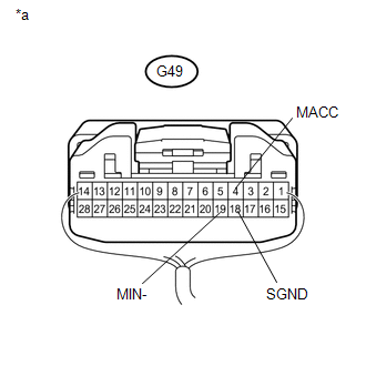
(a) Disconnect the G49 radio and display receiver assembly connector.
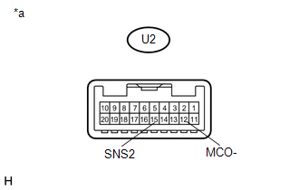
(b) Disconnect the U2 map light assembly (telephone microphone assembly) connector.
(c) Measure the resistance according to the value(s) in the table below.
Standard Resistance:
|
Tester Connection |
Condition |
Specified Condition |
|---|---|---|
|
G49-4 (MACC) - U2-14 (MACC) |
Always |
Below 1 Ω |
|
G49-5 (MIN+) - U2-13 (MCO+) |
Always |
Below 1 Ω |
|
G49-6 (SNS2) - U2-15 (SNS2) |
Always |
Below 1 Ω |
|
G49-19 (MIN-) - U2-12 (MCO-) |
Always |
Below 1 Ω |
|
G49-4 (MACC) - Body ground |
Always |
10 kΩ or higher |
|
G49-5 (MIN+) - Body ground |
Always |
10 kΩ or higher |
|
G49-6 (SNS2) - Body ground |
Always |
10 kΩ or higher |
|
G49-18 (SGND) - Body ground |
Always |
10 kΩ or higher |
|
G49-19 (MIN-) - Body ground |
Always |
10 kΩ or higher |
| NG | .gif) |
REPAIR OR REPLACE HARNESS OR CONNECTOR |
|
.gif)
|
2. |
INSPECT RADIO AND DISPLAY RECEIVER ASSEMBLY |
(a) Reconnect the G49 radio and display receiver assembly connector.
(b) Reconnect the U2 map light assembly (telephone microphone assembly) connector.
|
(c) Measure the voltage according to the value(s) in the table below. Standard Voltage:
|
|
(d) Measure the resistance according to the value(s) in the table below.
Standard Resistance:
|
Tester Connection |
Condition |
Specified Condition |
|---|---|---|
|
G49-18 (SGND) - Body ground |
Always |
Below 1 Ω |
|
G49-19 (MIN-) - Body ground |
Always |
Below 1 Ω |
|
*a |
Component with harness connected (Radio and Display Receiver Assembly) |
| NG | |
REPLACE RADIO AND DISPLAY RECEIVER ASSEMBLY |
|
|
3. |
INSPECT MAP LIGHT ASSEMBLY (TELEPHONE MICROPHONE ASSEMBLY) |
(a) Disconnect the U2 map light assembly (telephone microphone assembly) connector.
|
(b) Measure the resistance according to the value(s) in the table below. Standard Resistance:
|
|
| NG | |
GO TO STEP 5 |
|
|
4. |
INSPECT MAP LIGHT ASSEMBLY (TELEPHONE MICROPHONE ASSEMBLY) |
(a) Reconnect the G49 radio and display receiver assembly connector.
(b) Reconnect the U2 map light assembly (telephone microphone assembly) connector.
(c) Turn the ignition switch to ACC.
|
(d) Connect an oscilloscope to terminals 13 (MCO+) and 12 (MCO-) of the U2 map light assembly (telephone microphone assembly) connector. Text in Illustration
|
|

(e) Check the waveform of the telephone microphone assembly using the oscilloscope.
|
Result |
Proceed to |
|---|---|
|
A waveform synchronized with the voice input to the map light assembly (telephone microphone assembly) is output |
A |
|
A waveform synchronized with the voice input to the map light assembly (telephone microphone assembly) is not output |
B |
| A | |
PROCEED TO NEXT SUSPECTED AREA SHOWN IN PROBLEM SYMPTOMS TABLE |
|
|
5. |
REPLACE TELEPHONE MICROPHONE ASSEMBLY |
(a) Replace the telephone microphone assembly (See page
.gif) ).
).
(b) Check if the same malfunction recurs.
|
Result |
Proceed to |
|---|---|
|
Malfunction does not recur (returns to normal) |
A |
|
Malfunction recurs |
B |
| A | |
PROCEED TO NEXT SUSPECTED AREA SHOWN IN PROBLEM SYMPTOMS TABLE |
| B | |
REPLACE MAP LIGHT ASSEMBLY (TELEPHONE MICROPHONE ASSEMBLY) |
 Reverse Signal Circuit
DESCRIPTION
The radio and display receiver assembly receives a reverse signal from the park/neutral
position switch assembly.
WIRING DIAGRAM
PROCEDURE
1.
CHECK HARNESS A ...
 Radio Receiver Power Source Circuit
DESCRIPTION
This is the power source circuit to operate the radio and display receiver assembly.
WIRING DIAGRAM
CAUTION / NOTICE / HINT
NOTICE:
Inspect the fuses for circuits related to this sy ...
Other materials about Toyota 4Runner:
Disabling the TRAC/VSC systems (4WD models)
If the vehicle gets stuck in fresh snow or mud, the TRAC/VSC systems may
reduce power from the engine to the wheels. You may need to turn the system off
to enable you to rock the vehicle in order to free it.
Turning off the TRAC system only
To turn the ...
Diagnosis System
DIAGNOSIS SYSTEM
1. DIAGNOSIS
(a) If the skid control ECU detects a malfunction, the ABS and/or BRAKE warning
lights and the slip indicator lights come on in accordance with the trouble area
to warn the driver.
HINT:
The DTCs are simultaneously ...

0.0267