Toyota 4Runner: Mute Signal Circuit between Stereo Component Amplifier and Telematics Transceiver
DESCRIPTION
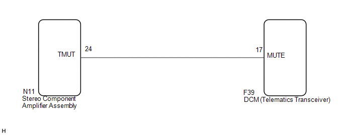
The DCM (telematics transceiver) sends a mute signal to the stereo component amplifier assembly.
The stereo component amplifier assembly controls the volume according to the mute signal from the DCM (telematics transceiver).
WIRING DIAGRAM
PROCEDURE
|
1. |
INSPECT DCM (TELEMATICS TRANSCEIVER) |
|
(a) Measure the voltage according to the value(s) in the table below. Standard Voltage:
|
|
| OK | .gif) |
PROCEED TO NEXT SUSPECTED AREA SHOWN IN PROBLEM SYMPTOMS TABLE |
|
.gif)
|
2. |
CHECK HARNESS AND CONNECTOR (STEREO COMPONENT AMPLIFIER ASSEMBLY - DCM (TELEMATICS TRANSCEIVER)) |
(a) Disconnect the N11 stereo component amplifier assembly connector.
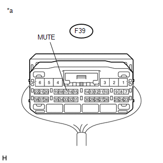
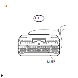
(b) Disconnect the F39 DCM (telematics transceiver) connector.
(c) Measure the resistance according to the value(s) in the table below.
Standard Resistance:
|
Tester Connection |
Condition |
Specified Condition |
|---|---|---|
|
N11-24 (TMUT) - F39-17 (MUTE) |
Always |
Below 1 Ω |
|
N11-24 (TMUT) - Body ground |
Always |
10 kΩ or higher |
| NG | |
REPAIR OR REPLACE HARNESS OR CONNECTOR |
|
|
3. |
INSPECT STEREO COMPONENT AMPLIFIER ASSEMBLY |
(a) Reconnect the N11 stereo component amplifier assembly connector.
(b) Disconnect the F39 DCM (telematics transceiver) connector.
|
(c) Measure the voltage according to the value(s) in the table below. Standard Voltage:
|
|
| OK | |
REPLACE DCM (TELEMATICS TRANSCEIVER) |
| NG | |
REPLACE STEREO COMPONENT AMPLIFIER ASSEMBLY |
 Mute Signal Circuit between Navigation Receiver Assembly and Stereo Component
Amplifier
Mute Signal Circuit between Navigation Receiver Assembly and Stereo Component
Amplifier
DESCRIPTION
This circuit sends a signal to the stereo component amplifier assembly to mute
noise. Because of that, the noise produced by changing the sound source ceases.
If there is an open in th ...
 AVC-LAN Circuit
DESCRIPTION
Each unit of the navigation system connected to the AVC-LAN (communication bus)
transfers the switch signals using the AVC-LAN.
If a short to +B or short to ground occurs in the AVC-LA ...
Other materials about Toyota 4Runner:
ECU Circuit (61)
DESCRIPTION
When the internal circuit of the side auto step controller ECU assembly malfunctions,
the side auto step controller ECU assembly halts the operation of the system.
DTC No.
DTC Detection Condition
Trouble Area
...
Back-up Power Source Circuit
DESCRIPTION
The back-up power source circuit for the air conditioning amplifier assembly
is shown below. Power is supplied even after the ignition switch is turned off and
is used for diagnostic trouble code memory, etc.
WIRING DIAGRAM
CAUTION / NOTIC ...

0.0275