Toyota 4Runner: Navigation Receiver Assembly Power Source Circuit
DESCRIPTION
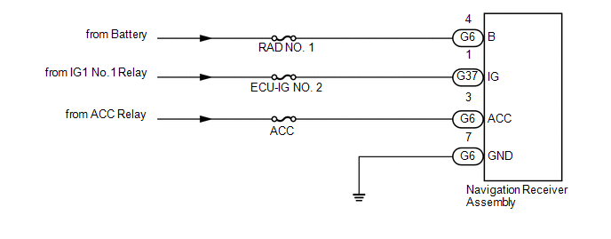
This is the power source circuit to operate the navigation receiver assembly.
WIRING DIAGRAM
CAUTION / NOTICE / HINT
NOTICE:
Inspect the fuses for circuits related to this system before performing the following inspection procedure.
PROCEDURE
|
1. |
CHECK HARNESS AND CONNECTOR (NAVIGATION RECEIVER ASSEMBLY - BATTERY, BODY GROUND) |
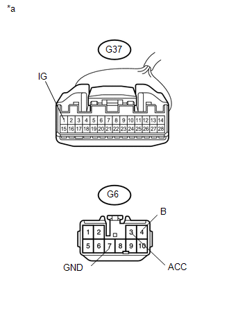
(a) Disconnect the G6 and G37 navigation receiver assembly connectors.
(b) Measure the resistance according to the value(s) in the table below .
Standard Resistance:
|
Tester Connection |
Condition |
Specified Condition |
|---|---|---|
|
G6-7 (GND) - Body ground |
Always |
Below 1 Ω |
|
(c) Measure the voltage according to the value(s) in the table below. Standard Voltage:
|
|
| OK | .gif) |
PROCEED TO NEXT SUSPECTED AREA SHOWN IN PROBLEM SYMPTOMS TABLE |
| NG | |
REPAIR OR REPLACE HARNESS OR CONNECTOR |
 Stereo Component Amplifier Power Source Circuit
DESCRIPTION
This circuit provides power to the stereo component amplifier assembly.
WIRING DIAGRAM
CAUTION / NOTICE / HINT
NOTICE:
Inspect the fuses for circuits related to this system before p ...

Other materials about Toyota 4Runner:
Fail-safe Chart
FAIL-SAFE CHART
1. FAIL-SAFE
This function minimizes the loss of ECT functions when a malfunction occurs in
a sensor or solenoid.
Malfunction Part
Function
No. 1 ATF temperature sensor
During a No. 1 ATF t ...
If your vehicle has to be stopped in an emergency
Only in an emergency, such as if it becomes impossible to stop the vehicle
in the normal way, stop the vehicle using the following procedure:
Steadily step on the brake pedal
with both feet and firmly depress it.
Do not pump the brake pedal repeatedly a ...

0.0221