Toyota 4Runner: Navigation Voice Circuit
DESCRIPTION
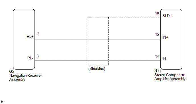
This circuit is used when the voice guidance in the navigation system is on or an incoming cellular phone voice in the "Bluetooth" hands-free system is heard.
Using this circuit, the navigation receiver assembly sends the signals to the stereo component amplifier assembly.
WIRING DIAGRAM
PROCEDURE
|
1. |
CHECK HARNESS AND CONNECTOR (NAVIGATION RECEIVER ASSEMBLY - STEREO COMPONENT AMPLIFIER ASSEMBLY) |
(a) Disconnect the G5 navigation receiver assembly connector.
(b) Disconnect the N11 stereo component amplifier assembly connector.
(c) Measure the resistance according to the value(s) in the table below.
Standard Resistance:
|
Tester connection |
Condition |
Specified condition |
|---|---|---|
|
G5-2 (RL+) - N11-15 (II1+) |
Always |
Below 1 Ω |
|
G5-6 (RL-) - N11-14 (II1-) |
Always |
Below 1 Ω |
|
N11-18 (SLD1) - Body ground |
Always |
10 kΩ or higher |
|
N11-14 (II1-) - Body ground |
Always |
10 kΩ or higher |
|
N11-15 (II1+) - Body ground |
Always |
10 kΩ or higher |
| OK | .gif) |
PROCEED TO NEXT SUSPECTED AREA SHOWN IN PROBLEM SYMPTOMS TABLE |
| NG | |
REPAIR OR REPLACE HARNESS OR CONNECTOR |
 Reverse Signal Circuit
DESCRIPTION
The navigation receiver assembly receives a reverse signal from the park/neutral
position switch assembly.
WIRING DIAGRAM
CAUTION / NOTICE / HINT
NOTICE:
After replacing t ...
 Microphone Circuit between Microphone and Navigation Receiver Assembly
DESCRIPTION
The navigation receiver assembly and map light assembly (telephone microphone
assembly) are connected to each other using the microphone connection detection
signal lines. ...
Other materials about Toyota 4Runner:
On-vehicle Inspection
ON-VEHICLE INSPECTION
PROCEDURE
1. INSPECT HOOD SUB-ASSEMBLY
(a) Check that the clearance measurements of areas A through E are within each
standard range.
Standard:
Area
Measurement
Area
Measurement
...
Steering Knuckle(for 2wd)
Components
COMPONENTS
ILLUSTRATION
ILLUSTRATION
Removal
REMOVAL
CAUTION / NOTICE / HINT
HINT:
Use the same procedure for the RH and LH sides.
The procedure listed below is for the LH side.
PROCEDURE
1. DISCONNECT CABLE FROM ...

0.0271