Toyota 4Runner: On-vehicle Inspection
ON-VEHICLE INSPECTION
PROCEDURE
1. INSPECT VOLTAGE INVERTER ASSEMBLY
HINT:
Remove interior parts so that the voltage inverter can be seen.
|
(a) Disconnect the voltage inverter connector. |
|
(b) Measure the voltage according to the value(s) in the table below.
Standard Voltage:
|
Tester Connection |
Switch Condition |
Specified Condition |
|---|---|---|
|
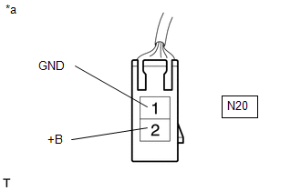
N20-1 (GND) - N20-2 (+B) |
Engine switch on (IG) |
11 to 14 V |
|
N20-1 (GND) - Body ground |
Always |
Below 1 V |
If the result is not as specified, repair or replace the harness or connector.
Text in Illustration|
*a |
Front view of wire harness connector (to Voltage Inverter Assembly) |
|
(c) Reconnect the voltage inverter connector. |
|
(d) Measure the voltage according to the value(s) in the table below.
Standard Voltage:
|
Tester Connection |
Switch Condition |
Specified Condition |
|---|---|---|
|
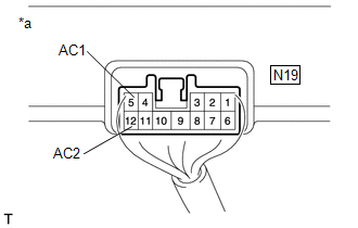
N19-5 (AC1) - N19-11 (AC2) |
Engine switch on (IG), main switch on |
AC 120 V |
If the result is not as specified, replace the voltage inverter assembly.
Text in Illustration|
*a |
Component with harness connected (Voltage Inverter Assembly) |
 Components
COMPONENTS
ILLUSTRATION
ILLUSTRATION
ILLUSTRATION
ILLUSTRATION
ILLUSTRATION
...
 Removal
REMOVAL
PROCEDURE
1. REMOVE REAR NO. 1 FLOOR STEP COVER (w/ Rear No. 2 Seat)
2. REMOVE QUARTER SCUFF PLATE RH (w/ Rear No. 2 Seat)
3. REMOVE REAR DOOR SCUFF PLATE RH
4. REMOVE REAR DOOR ...
Other materials about Toyota 4Runner:
A-TRAC Indicator Light does not Come ON
DESCRIPTION
The A-TRAC does not operate even if the A-TRAC switch is pressed under the following
conditions:
The TRAC or VSC system is faulty.
The temperature inside the hydraulic brake booster increases and the
A-TRAC operation is suspended ...
Rear seats
Vehicles without third row seats
Rear seat
Pull up the seatback angle adjustment lever until the lock is released.
Vehicles with third row seats
Second row seats
1. Seat position adjustment lever
2. Seatback angle adjustment lever
Third row seats
...

0.019