Toyota 4Runner: On-vehicle Inspection
ON-VEHICLE INSPECTION
PROCEDURE
1. INSPECT SEAT HEATER CONTROL SUB-ASSEMBLY LH
|
(a) Disconnect the b2 seat heater control sub-assembly LH connector. |
|
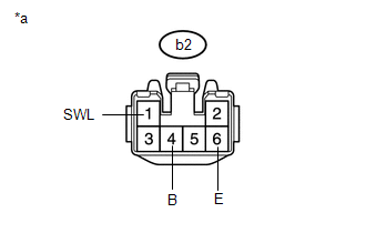
(b) Measure the resistance according to the value(s) in the table below.
Standard Resistance:
|
Tester Connection |
Condition |
Specified Condition |
|---|---|---|
|
b2-6 (E) - Body ground |
Always |
Below 1 Ω |
(c) Measure the voltage according to the value(s) in the table below.
Standard Voltage:
|
Tester Connection |
Switch Condition |
Specified Condition |
|---|---|---|
|
b2-1 (SWL) - b2-6 (E) |
Ignition switch ON Seat heater switch LH off |
Below 1 V |
|
Ignition switch ON Seat heater switch LH on |
11 to 14 V |
|
|
b2-4 (B) - b2-6 (E) |
Ignition switch off |
Below 1 V |
|
Ignition switch ON |
11 to 14 V |
|
*a |
Front view of wire harness connector (to Seat Heater Control Sub-assembly LH) |
If the result is not as specified, there may be a malfunction on the wire harness side.
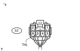
(d) Connect the b2 seat heater control sub-assembly LH connector.
|
(e) Measure the voltage according to the value(s) in the table below. Standard Voltage:
If the result is not as specified, the seat heater control sub-assembly LH may have a malfunction. |
|
2. INSPECT SEAT HEATER CONTROL SUB-ASSEMBLY RH
|
(a) Disconnect the a2 seat heater control sub-assembly RH connector. |
|
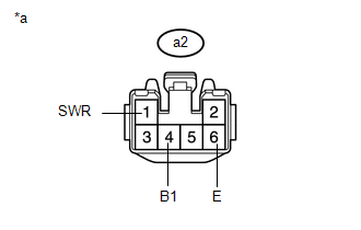
(b) Measure the resistance according to the value(s) in the table below.
Standard Resistance:
|
Tester Connection |
Condition |
Specified Condition |
|---|---|---|
|
a2-6 (E) - Body ground |
Always |
Below 1 Ω |
(c) Measure the voltage according to the value(s) in the table below.
Standard Voltage:
|
Tester Connection |
Switch Condition |
Specified Condition |
|---|---|---|
|
a2-1 (SWR) - a2-6 (E) |
Ignition switch ON Seat heater switch RH off |
Below 1 V |
|
Ignition switch ON Seat heater switch RH on |
11 to 14 V |
|
|
a2-4 (B1) - a2-6 (E) |
Ignition switch off |
Below 1 V |
|
Ignition switch ON |
11 to 14 V |
|
*a |
Front view of wire harness connector (to Seat Heater Control Sub-assembly RH) |
If the result is not as specified, there may be a malfunction on the wire harness side.
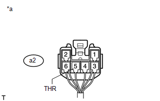
(d) Connect the a2 seat heater control sub-assembly RH connector.
|
(e) Measure the voltage according to the value(s) in the table below. Standard Voltage:
If the result is not as specified, the seat heater control sub-assembly RH may have a malfunction. |
|
 Problem Symptoms Table
PROBLEM SYMPTOMS TABLE
HINT:
Use the table below to help determine the cause of problem symptoms.
If multiple suspected areas are listed, the potential causes of the symptoms
are lis ...
 Seat Memory Switch
Components
COMPONENTS
ILLUSTRATION
Removal
REMOVAL
PROCEDURE
1. REMOVE FRONT DOOR LOWER FRAME BRACKET GARNISH LH
2. REMOVE NO. 2 DOOR INSIDE HANDLE BEZEL LH
3. REMOVE FRONT DOOR TR ...
Other materials about Toyota 4Runner:
Voice is not Recognized
CAUTION / NOTICE / HINT
NOTICE:
After replacing the navigation receiver assembly of vehicles subscribed to pay-type
satellite radio broadcasts, registration of the XM radio ID is necessary.
PROCEDURE
1.
CHECK CONDITION
(a ...
On-vehicle Inspection
ON-VEHICLE INSPECTION
PROCEDURE
1. CHECK STEERING PAD (VEHICLE NOT INVOLVED IN COLLISION)
(a) Perform a diagnostic system check (See page
).
(b) With the steering pad installed on the vehicle, perform a visual check. If
there are any defects as mention ...

0.0071