Toyota 4Runner: On-vehicle Inspection
ON-VEHICLE INSPECTION
PROCEDURE
1. CHECK SHIFT LOCK OPERATION
(a) Move the shift lever to P.
(b) Turn the ignition switch off.
(c) Check that the shift lever cannot be moved from P.
(d) Turn the ignition switch to on (IG), depress the brake pedal and check that the shift lever can be moved to other positions.
If the operation cannot be performed as specified, inspect the transmission floor shift assembly and shift lock control ECU.
2. CHECK SHIFT LOCK RELEASE BUTTON OPERATION
(a) When operating the shift lever with the shift lock release button pressed, check that the lever can be moved to any position.
If the operation cannot be performed as specified, check the transmission floor shift assembly.
3. CHECK SHIFT LOCK CONTROL ECU
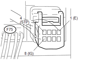
(a) Measure the voltage and resistance according to the value(s) in the table below.
HINT:
Do not disconnect the shift lock control ECU connector.
Standard Voltage and resistance:
|
Tester Connection |
Condition |
Specified Condition |
|---|---|---|
|
F75-8 (IG) - F75-1 (E) |
Ignition switch ON |
11 to 14 V |
|
F75-8 (IG) - F75-1 (E) |
Ignition switch off |
Below 1 V |
|
F75-4 (STP) - F75-1 (E) |
Brake pedal depressed |
11 to 14 V |
|
F75-4 (STP) - F75-1 (E) |
Brake pedal released |
Below 1 V |
|
F75-1 (E) - Body ground |
Always |
Below 1 Ω |
|
(b) Disconnect the shift lock solenoid connector from the shift lock control ECU. |
|
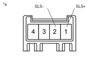
(c) Measure the voltage according to the value(s) in the table below.
HINT:
Do not disconnect the shift lock control ECU connector.
Standard Voltage:
|
Tester Connection |
Condition |
Specified Condition |
|---|---|---|
|
1 (SLS+) - 2 (SLS-) |
Ignition switch off |
Below 1 V |
|
1 (SLS+) - 2 (SLS-) |
Ignition switch ON |
Below 1 V |
|
Ignition switch ON and brake pedal depressed |
11 to 14 V |
|
*a |
Component without harness connected (Shift Lock Control ECU) |
If the result is not as specified, replace the transmission floor shift assembly.
4. CHECK SHIFT LOCK SOLENOID

(a) Disconnect the shift lock solenoid connector from the shift lock control ECU.
(b) Measure the resistance according to the value(s) in the table below.
Standard Voltage:
|
Tester Connection |
Condition |
Specified Condition |
|---|---|---|
|
1 (SLS+) - 2 (SLS-) |
Always |
101 to 123 Ω |
|
3 (E2) - 4 (P) |
Shift lever in P |
10 kΩ or higher |
|
3 (E2) - 4 (P) |
Shift lever not in P |
Below 1 Ω |
|
*a |
Component without harness connected: (Shift Lock Control Solenoid) |
(c) Apply 12 V of battery voltage to the shift lock solenoid and check that the valve moves and makes an operating noise.
OK:
|
Measurement Condition |
Specified Condition |
|---|---|
|
Solenoid moves and makes an operating noise |
If the result is not as specified, replace the transmission floor shift assembly.
 Components
COMPONENTS
ILLUSTRATION
...
 Removal
REMOVAL
PROCEDURE
1. REMOVE REAR CONSOLE BOX ASSEMBLY
(a) Remove the rear console box (See page ).
2. DISCONNECT TRANSMISSION CONTROL CABLE ASSEMBLY
(a) Move the shift lever to N.
(b ...
Other materials about Toyota 4Runner:
Sound Quality is Bad Only when CD is Played (Volume is Too Low)
PROCEDURE
1.
REPLACE CD AND RECHECK
(a) Replace the CD with a known good one and check that the malfunction disappears.
OK:
Malfunction disappears.
OK
END
NG
REPLACE RADIO AN ...
Washer Nozzle(for Rear Side)
Components
COMPONENTS
ILLUSTRATION
On-vehicle Inspection
ON-VEHICLE INSPECTION
CAUTION / NOTICE / HINT
HINT:
The washer fluid does not spray if the back door and back door glass are not
closed.
PROCEDURE
1. INSPECT REAR WASHER NOZZLE
(a) With ...

0.0254