Toyota 4Runner: Parts Location
Toyota 4Runner Service Manual / Vehicle Interior / Door Lock / Key Reminder Warning System / Parts Location
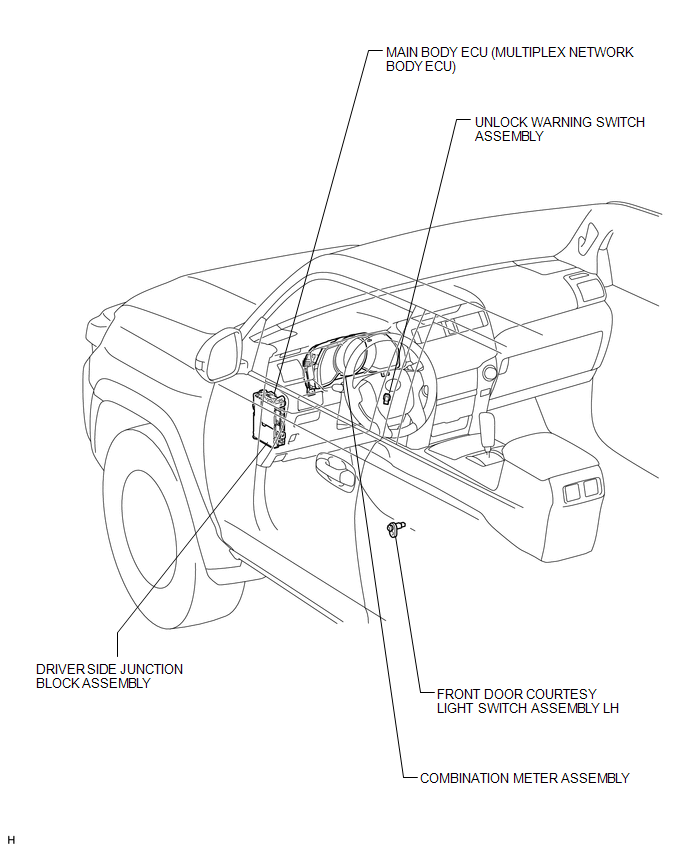
PARTS LOCATION
ILLUSTRATION

 System Diagram
SYSTEM DIAGRAM
Communication Table
Sender
Receiver
Signal
Line
Main body ECU (Multiplex network body ECU)
Combination meter a ...
Other materials about Toyota 4Runner:
Relay
On-vehicle Inspection
ON-VEHICLE INSPECTION
PROCEDURE
1. INSPECT DOME RELAY
(a) Measure the resistance according to the value(s) in the table below.
Standard Resistance:
Tester Connection
Condition
...
Installation
INSTALLATION
PROCEDURE
1. INSTALL REAR DIFFERENTIAL CARRIER ASSEMBLY
(a) Install a new gasket and the differential carrier assembly with the 10 nuts
and 10 washers.
Torque:
52 N·m {530 kgf·cm, 38 ft·lbf}
2. INSTALL REAR AXLE SHAFT LH
(a) Install t ...
© 2016-2026 | www.to4runner.net

0.0065
0.0065